There are numerous products out there to help with your design and documentation workflows, but which one is right for you. This blog article will look at the breadth of what AutoCAD offers in terms of products and specializations. There are many benefits to using AutoCAD, but this blog will focus on helping you decide which AutoCAD is right for you. For a more comprehensive breakdown of the benefits of AutoCAD, please see this blog post.
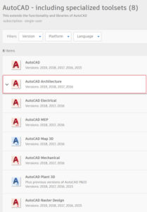
First and foremost, with the release of AutoCAD 2019, also known as “One AutoCAD”, Autodesk has moved away from the separate ‘vertical’ cad program subscriptions (i.e., Architecture, Electrical, Mechanical, MEP, etc.) and had now provided access to “specialized toolsets” for each discipline within the same subscription of AutoCAD. In other words, there is no longer a need to purchase different AutoCAD products depending on your industry – instead, you now get a subscription for AutoCAD. In addition to the ‘vanilla’ version of AutoCAD, you will have the various industry-specific specialized toolsets available for download.
Please note: Civil 3D has remained a separate product outside of the new offering (more on that below). So, while compatible with AutoCAD, Civil 3D will require a separate subscription if you intend to use it in conjunction with other cad software.
WHICH AUTOCAD IS BEST FOR ARCHITECTURE, MECHANICAL & ELECTRICAL ENGINEERS?
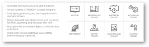
These industry-specific toolsets provide features and libraries specific to certain trades or disciplines that are useful in automating and streamlining the design and documentation process, whether it is 2D drafting or 3D modeling.
By providing automated workflows and collections of intelligent parts, symbols, and building objects, the new AutoCAD offers more flexibility in its functionality in the ever-evolving world of BIM. So, let’s take a look at a brief overview of the various toolset options so you can decide which is right for you.
Below are the products available to you as part of the “AutoCAD including specialized toolsets” package:
Used by electrical engineers and users involved in documenting electrical control systems.
Supplies tools to create panel layouts, schematic diagrams, and other electrical drawings.
65,000+ intelligent symbols.
New/Featured Tools:
Automatic Report Generation: Generate and update customized reports.
Customer & Supplier Collaboration: Easily share DWG drawings with stakeholders.
Easily Manage Projects: Use folders to organize drawings and reorder files for electrical drafting purposes.
AutoCAD Map 3D
Designed for users who need to utilize and maintain CAD and GIS data for planning, design, and data management.
Equips users with tools to create, maintain, and communicate mapping and GIS information within the AutoCAD drawing environment.
Manages GIS data and uses task-based tools to aggregate with design data.
New/Featured Tools:
Use Feature Data Objects (FDO) Technology: Work with spatial data from a variety of CAD and GIS data formats and coordinate systems.
Connect to ArcGIS: Streamline the flow of data between ArcGIS and Map 3D and keep features information up to date.
Convert Data Between DWG and GIS Data: Perform high-fidelity data conversions using MapImport and MapExport.
AutoCAD Mechanical
Used by manufacturing, product, and mechanical design professionals.
Provides tools to automate mechanical engineering tasks such as generating machine components, dimensioning, and creating a bill of materials.
70,000+ intelligent objects.
Key/Featured Tools:
Layer Management: Isolate and restore layer groups and specify line types and line weights.
Hidden Lines: Update geometry automatically when a change occurs and minimize rework.
Machinery Generators & Calculators: Efficiently analyze designs, including shaft, spring, belt, and cam generators.
AutoCAD MEP
Used by mechanical, electrical, plumbing, and fire protection professionals.
Supplies tools to help draft, design, and document MEP building systems in both 2D and 3D cad.
10,500+ intelligent MEP objects.
Key/Featured Tools:
MEP Workspaces: Workspace environments include individual palettes and domain-specific ribbons.
AutoCAD Block Conversion: Batch-convert single or multiple blocks and symbols.
Styles Browser: Get more MEP components and add folders to the Content Library.
AutoCAD Plant 3D
Used for 3D design of plant models.
Provides tools to generate and share isometrics, orthographic, and materials reports.
Also provides tools to create schematic diagrams, plant layouts, and other drawings necessary for plant design.
400+ intelligent plant objects.
Key/Featured Tools:
Collaboration for Plant 3D: Collaborate on plant models across project teams and maintain compliance requirements, all in a cloud-based environment.
Quick P&ID Drafting: In-context AutoCAD commands help P&ID drafting easier.
Data Validation: Quickly identify possible errors by scanning P&IDs for data consistency according to user-defined rules.
AutoCAD Raster Design
Designed to help users edit scanned drawings and convert raster images to DWG objects.
Key/Featured Tools:
Image Editing & Cleanup: Despeckle, bias, mirror, and touch up your images.
Raster Entity Manipulation (REM): Use standard AutoCAD commands on raster regions and primitives.
Vectorization Tools: Create lines and polylines from raster images, and convert raster files into vector drawings.
Image Transformation Functionality: Show and analyze geo images in Civil 3D engineering software and the AutoCAD Map 3D toolset.
To find out more about AutoCAD including specialized toolsets, click here.
For an overview of new features in AutoCAD 2021, please see here.
WHICH AUTOCAD IS BEST FOR CIVIL ENGINEERS AND INFRASTRUCTURE PROJECTS?
As mentioned above, AutoCAD Civil 3D is still a separate product outside of the new bundled offering of AutoCAD including specialized toolsets.
AutoCAD Civil 3D is built on top of AutoCAD Map 3D and the base AutoCAD. It has all of the features of both but also provides dynamic tools for civil engineering tasks such as grading, road design, pipe networks, and profiles.
Civil 3D is a civil engineering design software that supports BIM with integrated features to improve drafting, design, and construction documentation.
Key/Featured Tools:
Collaboration for Civil 3D: Securely access Civil 3D files, data shortcuts, and xrefs from multiple locations and companies, all in a common data environment.
Connector for ArcGIS: Streamline the flow of data between ArcGIS and Civil 3D. Access the latest data and keep features information up to date. Task-based tools to manage GIS data and aggregate GIS data with design data.
Dynamo for Civil 3D: Use the Dynamo visual scripting environment to develop routines that automate repetitive design tasks and expedite workflows.
Bridge Design: Coordinate workflows more efficiently across the various disciplines working on complex bridge design projects.
Pressure Network: Use enhanced tools for more efficient pressure pipe network layout and design.
New Transit & Rail Design Features: An expanded toolkit for transit and rail design including spirals, dynamic alignments, profiles, and superelevation design.
Design & Documentation: Create plans, profiles, and cross-sections for roads, land development, and other civil designs. Consistent project standards with drawings organized in a project-based structure.
Access to Information: Standard data schema, automated business workflows, and report templates for Electric North America, Electric Europe, Water, Wastewater, Gas industry.
Intelligent Objects: Intelligent civil objects that interact to create interconnected designs along with configurable styles to conform to nearly any graphical standards.
To find out more about AutoCAD Civil 3D, click here.
SUMMARY
Choosing the right AutoCAD software can be confusing. With the all-in-one offering created by Autodesk for AutoCAD starting in 2019, that has become a little easier of a decision. You may still have the decision as to whether you want to move forward with AutoCAD or possibly go to a solution that leans more toward full BIM, like Revit. Or, you may be looking at other 3D modeling software like Rhino, Solidworks, Sketchup, or again even Revit.
These decisions will come down to what you are trying to accomplish with the software – are you drafting and creating construction documentation, are you preparing models for renderings or 3D printing, or are you simply looking for the most affordable solution that meets the need of your team at this time?
You want the features and licensing options that make you and your team more productive. The truth is – it isn’t just the price you pay that matters. The right software will likely include features that save you so much time and labor costs that it more than pays for itself.
There are a lot of options out there. This blog, hopefully, helps walk you through the options when considering AutoCAD as the solution that best fits your needs.
Technology is transforming the way that buildings and infrastructure are designed, constructed, and operated. It’s helping improve decision-making and performance across the buildings and infrastructure lifecycle.
To learn more about how Autodesk’s Connected BIM processes go beyond design, leveraging the power of the cloud to help make possible practically anytime, anywhere, collaboration, data continuity across a project, and provide deep insight to help improve decision-making,
You can view the recording of all of the Connected BIM Webinar Series here.
Access your Project Data throughout the Building Construction Lifecycle
How do you collaborate and access project data throughout the building construction lifecycle? Review our previously recorded webinar to learn how Collaboration for Revit and the BIM 360 Team service from Autodesk can empower a project team to collaborate, those in the field to better anticipate and act, and those in the back office to optimize and manage all aspects of construction performance.
Integrated BIM Workflows across the Lifecycle of Buildings
Technology is radically disrupting the way buildings and infrastructure is designed, built, and used. As Physical and digital technology come together to create endless possibilities for designing, buildings, and operating buildings and infrastructure, it’s important to embrace BIM. Watch our webinar recording to learn how BIM will give you the opportunity to dramatically improve margins and resilience, capitalize on an increasingly globalized construction market, and deliver better outcomes for your clients.
Explore Infrastructure in the Era of Connection
Technology is radically disrupting the way buildings and infrastructure is designed, built, and used. Discover how Autodesk is connecting to the future with tightly connected BIM tools and processes for the buildings and infrastructure lifecycle.
Do you have any questions on how Autodesk’s Connected BIM processes can help you leverage the power of the cloud? Let us know how we can help.
There’s an old saying that I’m sure you’ve heard that goes “you won’t know until you try”. While it’s one of those phrases that’s been around long before computers were in every office, it remains modern enough to be very relevant to working with software. I found myself thinking about this phrase when a client asked if they could have a Civil 3D surface printed on our 3D Printer, a 3D Systems CJP Project 660Pro.
It may sound obvious, but the only prerequisite for printing anything in 3D is that the object has a width, depth, and height. A Civil 3D surface object, while made up of X, Y, and Z points, is only a two-dimensional object since it has no thickness. The first hurdle would then be to add some “thickness” or height to that surface to make it printable.
If you are a Civil 3D user you may think, “well that’s easy, just use the Extract Solids from Surface”. And while that is exactly what crossed my mind when I started thinking about how to print a Civil 3D surface, it turns out that the Extract Solids from Surface does not work for very complex geometries. This command is great for extracting out solids from corridors and smaller surfaces, but it couldn’t generate a solid for a heavily graded 70-acre subdivision with 100’ of elevation difference between its low and high points.
As I didn’t have rights to use the surface described above when writing this blog, I am instead using another surface to illustrate the steps. For all intents and purposes, these steps will work for any surface.
Exporting Civil 3D Data for 3ds Max
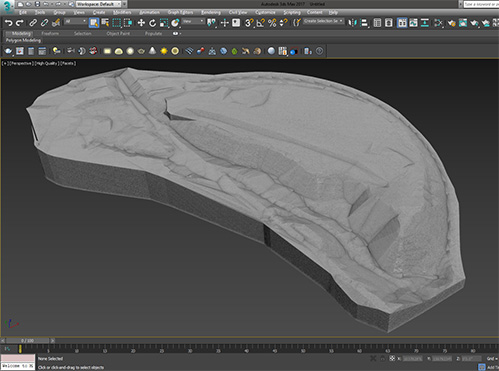
Met with failure, I turned to 3ds Max, the most powerful geometry editing software in the AEC Collection. I had many options to choose from when importing the Civil 3D surface into 3ds Max, but I narrowed it down to two options.
The first option would use Civil View to exchange Civil 3D object data with 3ds Max using a VSP3D file. The second option is to export a LANDXML file from Civil 3D and then import that file into 3ds Max.
I ended up choosing the latter option since it automatically generated polygons in the various HIDE boundaries found on the Civil 3D surface I was using. While I lost a marginal amount of fidelity from the original surface, using LANDXML created a gapless surface which we preferred for the 3D Print.
Exporting a LANDXML file from Civil 3D is as easy as right-clicking the surface in the Prospector and selecting Export LandXML… Importing the LANDXML file into 3ds Max is equally simple; click on the File menu, choose Import and select the LANDXML file. You should uncheck Smooth Surface in the Object Creation Options to preserve the Civil 3D surface geometry.
Creating a watertight model
Unlike the Extract Solids from Surface command in Civil 3D, I simply had to create a watertight poly surface or mesh in 3ds Max. A watertight model is defined as an object that doesn’t have any naked edges. McNeel’s website makes a great analogy when defining a watertight object; “another way to understand a solid is to see it as a balloon. If there is even a pin prick size hole, it will deflate. Thus it is not air/watertight, not volumetric. A solid is a volume. A solid is its outer surfaces, once they are completely joined”
The LANDXML import provides me with a editable mesh in 3ds Max. To manipulate the geometries in the mesh to create the watertight solid I previously mentioned, follow these steps:
Select the Editable Mesh and choose the Element sub-object levels in the modifier stack
Click on any part of the surface and you will see the entire mesh highlight
In the Edit Geometry rollout enter in an Extrude value; I will use 500’
Switch the to the Edge sub-object level and press the Select Open Edges button in the Edit Geometry rollout
With the open edges selected, toggle the Top view and select View Align from the Edit Geometry rollout. This will flatten the edges to the same Z value
Choose the Face sub-object level and drawing a Crossing Selection through the recently extruded faces
Select the Detach button from the Edit Geometry rollout to create new object from those faces
De-select the original mesh and select the detached mesh
Right-click and choose Convert To: Convert to Editable Poly from the Transform Quad
Select the Editable Poly object, activate its Border sub-object level, and select the open border
From the Graphite Modeling Tools, select Cap Poly from the Geometry (All) Panel in the Modeling ribbon
Activate its Polygon sub-object level and select the bottom polygon cap
Press the W key to activate the Move gizmo and raise the Polygon along the Z axis to the desired height
Deselect all sub-object levels, select the Editable Poly
Right-click and choose Convert To: Convert to Editable Mesh from the Transform Quad
De-select the detached mesh and select the original mesh
Select Attach from the Edit Geometry rollout
Choose the detached mesh to join it to the original mesh creating a watertight mesh
Despite the extensive list of steps, the process is straightforward if you are familiar with 3ds Max. The video below illustrates all these steps to make it easier to follow along.
Create a file for 3D Printing
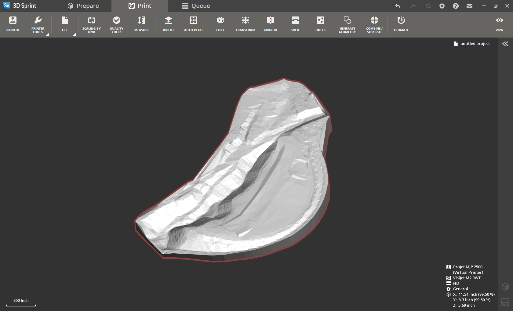
Once the geometry has been edited to be watertight, export the geometry to an STL (STereoLithography) file. In order to send our 3D print jobs, we use an application called 3D Sprint. 3D Sprint can import the STL, check for any geometry errors, and scale the model so it can be printed. The screenshot below shows the 3ds Max geometry ready to be printed.
Features the latest informative and technical content provided by our industry experts for designers, engineers, and construction firms and facility owners.