


Understanding AutoCAD Scale Factor
By Pook Villegas | CAD, Collaboration, Data Management
When creating a drawing in AutoCAD, the scale factor is one of the most important things to consider. This is because the scale factor determines the size and proportion of all elements within the drawing. Properly understanding and use of scale factors can significantly impact the accuracy and precision of your drawings, allowing you to create high-quality designs.
In this guide, I will discuss the concept of scale factor in AutoCAD, how to use it effectively, and what best practices to follow.
What is an AutoCAD Scale Factor?
Scale factor in AutoCAD software is a numerical value that represents the relationship between the size of an object in real life and its representation on the drawing. It is expressed as a ratio or fraction, with 1:1 representing full size or actual scale.
For example, if a drawing element is 1 inch in real life and its representation on the drawing is also 1 inch, then the scale factor would be 1:1.
However, most drawings are not created at full size due to space constraints. This is where scale factors come into play. Using scale factors, we can shrink or enlarge elements on the drawing to fit within the desired drawing size. This allows us to create detailed and accurate drawings that can be easily understood.
How To Calculate and Apply Scale Factors in AutoCAD
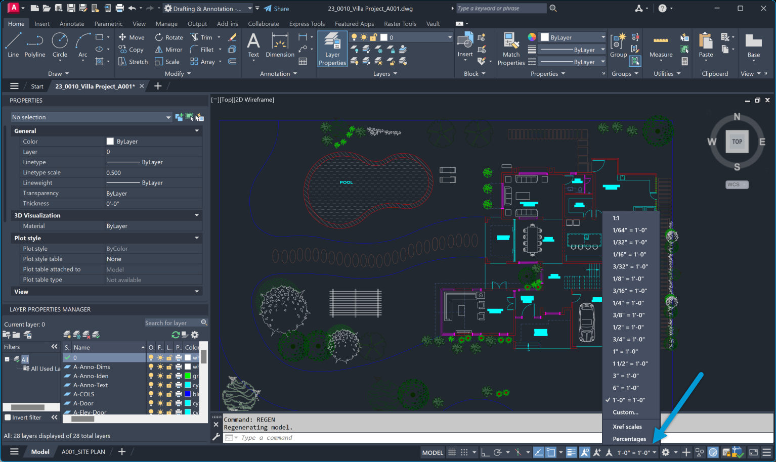
AutoCAD offers a variety of options to set the scale factor for your drawing. One way is by using the ‘SCALE’ command, where you can specify a reference length and enter the desired size on the drawing.
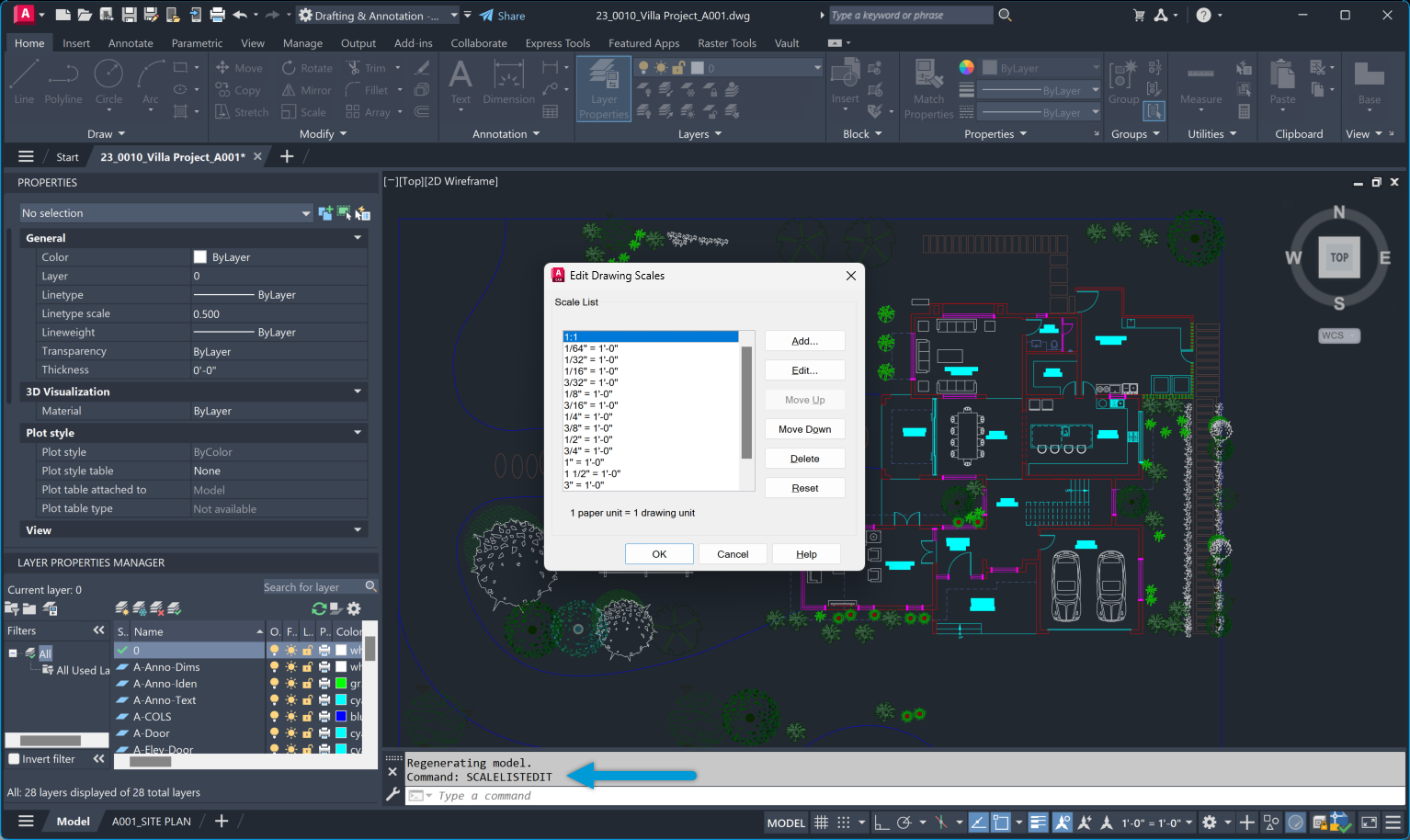
Alternatively, you can use preset scale factors such as 1/2xp (half size) or 2xp (double size) through the ‘SCALELISTEDIT’ command. This allows for quick and easy scaling of elements in your drawing.
It is essential to note that scale factors can be applied globally to the entire drawing or individually to specific elements. Combining both methods can provide more flexibility and accuracy in your designs.
Scale Factor Methods in AutoCAD
There are multiple methods of specifying scale factors in AutoCAD, including:
Absolute Scale Factor
This method involves entering a specific value for the scale factor, such as 1:2 or 3/4xp. The elements in the drawing will be scaled accordingly. The benefit of using this method is that it allows for precise and accurate scaling.
Relative Scale Factor
In this method, the scale factor is relative to a reference length specified by the user. This means that any element in the drawing can be used as a reference, and all other elements will be scaled accordingly. This provides more flexibility when working with complex or irregularly sized objects.
Fit Scale Factor
Using the ‘SCALE’ command with a scale factor of 0 will result in the drawing elements being scaled to fit within the desired size. This method is useful when resizing an entire drawing quickly without worrying about specific scale factors.
Scale by Reference
This method involves selecting a reference object and specifying the desired size, and AutoCAD will automatically calculate the scale factor needed. This is especially useful when working with drawings that require a specific ratio or proportion.
Annotative Scale Factor
With the introduction of annotative objects in AutoCAD, scale factors can now also be applied to annotations such as dimensions and text. This ensures these elements appear consistent and legible regardless of the drawing size.
Importance of AutoCAD Scale Factor in Design
Understanding and using scale factors correctly is crucial in creating accurate and precise drawings. Without it, elements on the drawing may appear distorted or out of proportion, leading to errors and misinterpretations.
Proper understanding of scale factors also allows for consistency in drawings. When working on a project with multiple drawings, using consistent scale factors ensures that all elements are accurately sized and proportioned, resulting in a cohesive and professional look.
Additionally, scale factors also play a crucial role in printing drawings. By correctly setting the scale factor, we can ensure that the printed version of the drawing is to scale and matches the desired dimensions.
AutoCAD Scale Factors Charts
Two types of scale factor charts are commonly used in AutoCAD: the architectural and engineering scale charts. These charts provide a quick reference for commonly used scales, making choosing a suitable scale factor easier.
Architectural Scales
| Drawing Scale | Scale Factor | Viewport Scale | Decimal Scale |
|---|---|---|---|
| 1/16″ = 1′-0″ | 192 | 1/192xp | .0625″ = 1′-0″ |
| 3/32″ = 1′-0″ | 128 | 1/128xp | .09375″ = 1′-0″ |
| 1/8″ = 1′-0″ | 96 | 1/96xp | .125″ = 1′-0″ |
| 3/16″ = 1′-0″ | 64 | 1/64xp | .1875″ = 1′-0″ |
| 1/4″ = 1′-0″ | 48 | 1/48xp | .25″ = 1′-0″ |
| 3/8″ = 1′-0″ | 32 | 1/32xp | .375″ = 1′-0″ |
| 1/2″ = 1′-0″ | 24 | 1/24xp | .50″ = 1′-0″ |
| 3/4″ = 1′-0″ | 16 | 1/16xp | .75″ = 1′-0″ |
| 1″ = 1′-0″ | 12 | 1/12xp | 1″ = 1′-0″ |
| 1 1/2″ = 1′-0″ | 8 | 1/8xp | 1.5″ = 1′-0″ |
| 3″ = 1′-0″ | 4 | 1/4xp | 3″ = 1′-0″ |
Engineering Scales
| Drawing Scale | Scale Factor | Viewport Scale |
| 1″ = 10′-0″ | 120 | 1/120xp |
| 1″ = 20′-0″ | 240 | 1/240xp |
| 1″ = 30′-0″ | 360 | 1/360xp |
| 1″ = 40′-0″ | 480 | 1/480xp |
| 1″ = 50′-0″ | 600 | 1/600xp |
| 1″= 60′-0″ | 720 | 1/720xp |
| 1″ = 70′-0″ | 840 | 1/840xp |
| 1″ = 80′-0″ | 960 | 1/960xp |
| 1″ = 90′-0″ | 1080 | 1/1080xp |
| 1″ = 100′-0″ | 1200 | 1/1200xp |
Common Issues And Solutions Related to AutoCAD Scale Factors
Some common problems that users may face when working with scale factors in AutoCAD include:
Mismatch or inconsistency of units and settings
When working on drawings that require specific units and settings, it is important to ensure that the scale factors are set accordingly. For example, working with architectural drawings in inches while the scale factor is set to millimeters will result in an inaccurate drawing.
Distorted elements or annotations
If elements or annotations appear distorted or out of proportion, it may be due to incorrect scale factors being applied. Double-checking the scale factor and reference lengths used can help resolve this issue.
Difficulty in printing to scale
One common issue when printing is that the drawing may not be to scale, even if the correct scale factor has been set. This can be caused by incorrect printer or plotter settings. It is essential to check these settings before printing to ensure accurate results. I once faced a printing issue due to this. Despite setting the correct scale in AutoCAD, the printed drawings were consistently off. After much troubleshooting, I discovered that the plotter had a default setting that scaled all outputs to fit the paper size, overriding my AutoCAD settings. Adjusting the plotter settings resolved the issue, underscoring the importance of verifying both software and hardware settings.
Incorrect or inappropriate use of scale factors and transformations
It is essential to use scale factors and transformations correctly, depending on the type of drawing and its intended purpose. Using an inappropriate scale factor or transformation can lead to errors in the final product. The solution is carefully selecting the appropriate method and double-checking all settings before proceeding with the drawing.
Human error
Human error is also a common cause of issues related to scale factors in AutoCAD. Pay close attention when setting scale factors and double-check all settings before finalizing any drawing.
Best Practices For Using Scale Factors in AutoCAD
To ensure accurate and efficient use of scale factors in AutoCAD, here are some best practices to keep in mind:
- Familiarize yourself with the different methods of specifying scale factors and choose the most appropriate one for your drawings.
- Double-check all settings and units before applying a scale factor to avoid errors.
- Consider using multiple scale factors on individual elements to achieve the desired result.
- Use scale factor charts as a quick reference when working with standard scales.
- Regularly check for and correct any inconsistencies or errors related to scale factors in your drawings.
Understanding and effectively using scale factors is crucial for producing accurate and professional drawings in AutoCAD. Familiarizing yourself with the various methods of specifying scale factors and implementing best practices can help you achieve the desired results without any issues.
INDUSTRIES: Architecture, Buildings, Interior Design