As of April 30, 2025, we’re proud to announce our exciting new chapter. | Read more here.
Revit schedules are powerful tools that provide architects and engineers with a structured way to organize and manage data within a 3D model. However, there are times when you might need to export this data to Microsoft Excel for further analysis, collaboration, or reporting. Here, we will walk you through the schedule exporting process step by step. Then, we will also break down some best practices and common issues to ensure you can manage your Revit data effectively.
Exporting schedules to Excel is a simple process that boils down to locating and navigating the appropriate menus within Revit’s User interface. Below are the six easy steps you can take to export your first schedule.
First, launch Autodesk Revit and open the project containing the schedule you want to export. Make sure your Revit project is fully loaded and navigate to the view containing the schedule.
In Revit, schedules are typically found under the “Project Browser” on the left side of the screen. Locate the schedule you wish to export and double-click to open it. This view should display all the parameters and data you’ve set up in your Revit schedule.
With the schedule view open, go to the “File” menu at the top left corner of the screen. Select “Export” from the dropdown menu, then choose “Reports” and finally “Schedules.”
A dialog box will appear, prompting you to configure the export settings. Here, you can choose the file format for the export. To export to Excel, select either CSV (Comma Delimited) or TXT (Tab Delimited) file format. Both of these formats can be easily imported into an Excel spreadsheet.
You will also be presented with various options regarding the appearance of your exported schedule, including:
Check all the options that apply to the data you wish to export.
Once you’ve selected the desired format, click “OK” and choose a location to save your file. Give your file an appropriate name, such as “Revit_Schedule_Export,” and click “Save.”
Navigate to the saved file on your computer. Right-click the file and choose “Open with Excel.” Excel will open and display your Revit schedule data in a structured format. Congratulations, you’ve just exported your first Revit Schedule to Excel!
To ensure that your schedules are accurate and easy to read, consider implementing these best practices when exporting them into Excel.
Before exporting, ensure that your Revit schedule is clean and well-organized. Remove any unnecessary parameters or data that you don’t need. This will make the Excel file easier to work with and more readable.
Consistent naming conventions for parameters and schedules can help maintain clarity when you export to Excel. This practice is particularly useful for large projects with extensive data.
Consider using Revit plugins such as Ideate BIMLink or Dynamo. These tools can enhance the functionality of your exports, providing more control over the data and how it is transferred to Excel.
Before and after exporting your Revit schedules to Excel, it’s important to make sure your data is accurate. Double-check that all parameters and values are correctly represented in the schedule.
While exporting Revit schedules to Excel, you might encounter some of the following issues. Here are a few troubleshooting tips that can help you resolve them:
If your data appears jumbled in Excel, check the delimiter settings during export. Ensure you selected the correct format (CSV or TXT) that matches your Excel import settings.
Sometimes, not all data is exported. Before exporting, ensure that all parameters are included in the schedule view. If using add-ins, double-check their settings for any restrictions.
Sometimes, certain elements in your schedule might be hidden or filtered out, leading to an incomplete export. Before exporting, ensure all relevant elements are visible and included in the schedule view. Check for any applied filters or hidden columns that could affect the export.
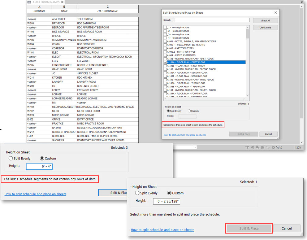
Large schedules can slow down the export process. Breaking down the schedule into smaller segments can help manage performance issues.
Knowing how to export schedules from Revit to Excel is a valuable skill that can streamline your workflow and enhance your data management capabilities. With these tips and a clear understanding of the process, you’ll be able to harness the full potential of your schedule data, making project management and reporting more effective and helping you stay competitive and productive in your field.

When creating a drawing in AutoCAD, the scale factor is one of the most important things to consider. This is because the scale factor determines the size and proportion of all elements within the drawing. Properly understanding and use of scale factors can significantly impact the accuracy and precision of your drawings, allowing you to create high-quality designs.
In this guide, I will discuss the concept of scale factor in AutoCAD, how to use it effectively, and what best practices to follow.
Scale factor in AutoCAD software is a numerical value that represents the relationship between the size of an object in real life and its representation on the drawing. It is expressed as a ratio or fraction, with 1:1 representing full size or actual scale.
For example, if a drawing element is 1 inch in real life and its representation on the drawing is also 1 inch, then the scale factor would be 1:1.
However, most drawings are not created at full size due to space constraints. This is where scale factors come into play. Using scale factors, we can shrink or enlarge elements on the drawing to fit within the desired drawing size. This allows us to create detailed and accurate drawings that can be easily understood.
AutoCAD offers a variety of options to set the scale factor for your drawing. One way is by using the ‘SCALE’ command, where you can specify a reference length and enter the desired size on the drawing.
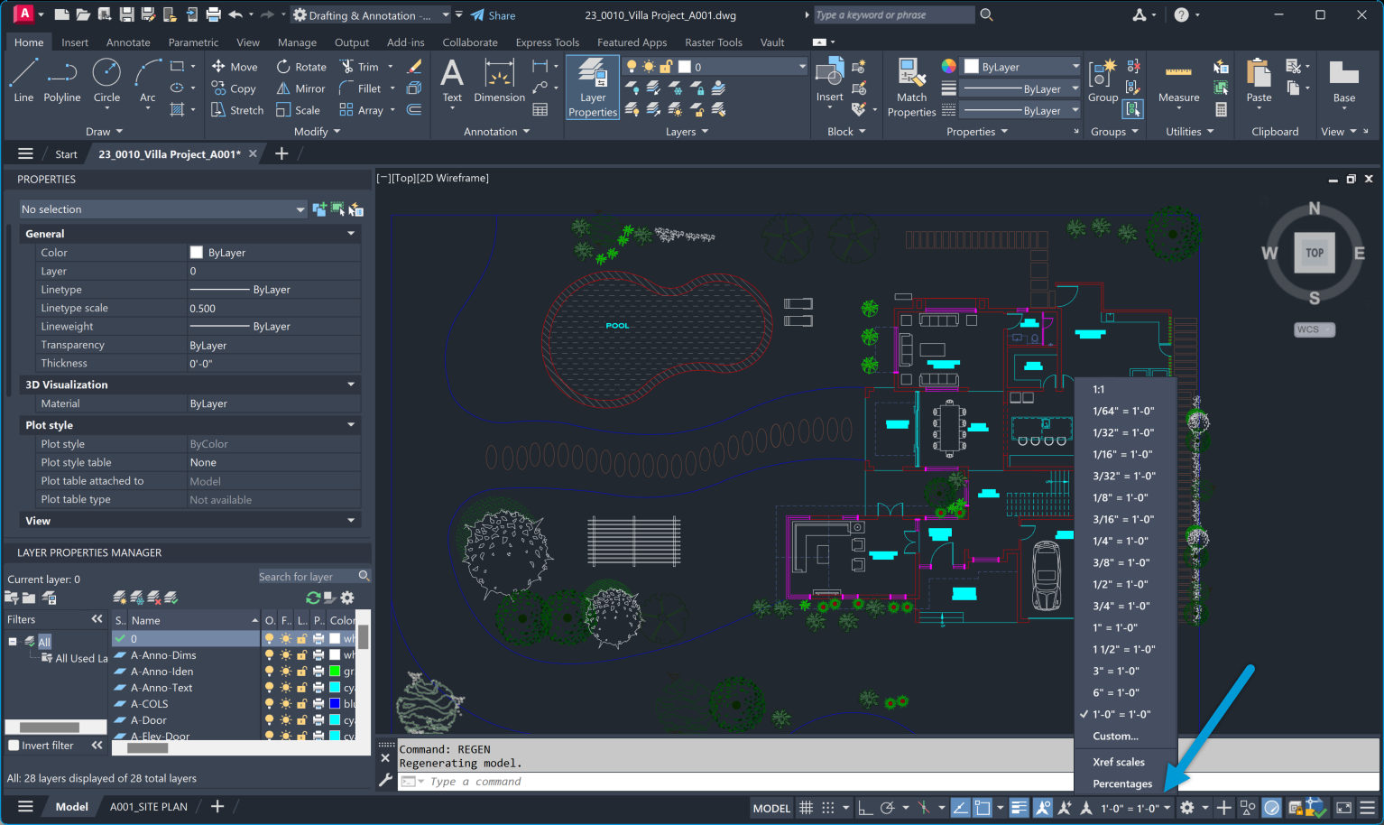
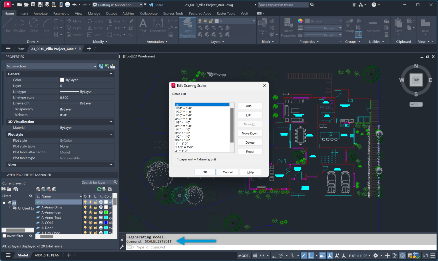
Alternatively, you can use preset scale factors such as 1/2xp (half size) or 2xp (double size) through the ‘SCALELISTEDIT’ command. This allows for quick and easy scaling of elements in your drawing.
It is essential to note that scale factors can be applied globally to the entire drawing or individually to specific elements. Combining both methods can provide more flexibility and accuracy in your designs.
There are multiple methods of specifying scale factors in AutoCAD, including:
This method involves entering a specific value for the scale factor, such as 1:2 or 3/4xp. The elements in the drawing will be scaled accordingly. The benefit of using this method is that it allows for precise and accurate scaling.
In this method, the scale factor is relative to a reference length specified by the user. This means that any element in the drawing can be used as a reference, and all other elements will be scaled accordingly. This provides more flexibility when working with complex or irregularly sized objects.
Using the ‘SCALE’ command with a scale factor of 0 will result in the drawing elements being scaled to fit within the desired size. This method is useful when resizing an entire drawing quickly without worrying about specific scale factors.
This method involves selecting a reference object and specifying the desired size, and AutoCAD will automatically calculate the scale factor needed. This is especially useful when working with drawings that require a specific ratio or proportion.
With the introduction of annotative objects in AutoCAD, scale factors can now also be applied to annotations such as dimensions and text. This ensures these elements appear consistent and legible regardless of the drawing size.
Importance of AutoCAD Scale Factor in Design
Understanding and using scale factors correctly is crucial in creating accurate and precise drawings. Without it, elements on the drawing may appear distorted or out of proportion, leading to errors and misinterpretations.
Proper understanding of scale factors also allows for consistency in drawings. When working on a project with multiple drawings, using consistent scale factors ensures that all elements are accurately sized and proportioned, resulting in a cohesive and professional look.
Additionally, scale factors also play a crucial role in printing drawings. By correctly setting the scale factor, we can ensure that the printed version of the drawing is to scale and matches the desired dimensions.
Two types of scale factor charts are commonly used in AutoCAD: the architectural and engineering scale charts. These charts provide a quick reference for commonly used scales, making choosing a suitable scale factor easier.
| Drawing Scale | Scale Factor | Viewport Scale | Decimal Scale |
|---|---|---|---|
| 1/16″ = 1′-0″ | 192 | 1/192xp | .0625″ = 1′-0″ |
| 3/32″ = 1′-0″ | 128 | 1/128xp | .09375″ = 1′-0″ |
| 1/8″ = 1′-0″ | 96 | 1/96xp | .125″ = 1′-0″ |
| 3/16″ = 1′-0″ | 64 | 1/64xp | .1875″ = 1′-0″ |
| 1/4″ = 1′-0″ | 48 | 1/48xp | .25″ = 1′-0″ |
| 3/8″ = 1′-0″ | 32 | 1/32xp | .375″ = 1′-0″ |
| 1/2″ = 1′-0″ | 24 | 1/24xp | .50″ = 1′-0″ |
| 3/4″ = 1′-0″ | 16 | 1/16xp | .75″ = 1′-0″ |
| 1″ = 1′-0″ | 12 | 1/12xp | 1″ = 1′-0″ |
| 1 1/2″ = 1′-0″ | 8 | 1/8xp | 1.5″ = 1′-0″ |
| 3″ = 1′-0″ | 4 | 1/4xp | 3″ = 1′-0″ |
| Drawing Scale | Scale Factor | Viewport Scale |
| 1″ = 10′-0″ | 120 | 1/120xp |
| 1″ = 20′-0″ | 240 | 1/240xp |
| 1″ = 30′-0″ | 360 | 1/360xp |
| 1″ = 40′-0″ | 480 | 1/480xp |
| 1″ = 50′-0″ | 600 | 1/600xp |
| 1″= 60′-0″ | 720 | 1/720xp |
| 1″ = 70′-0″ | 840 | 1/840xp |
| 1″ = 80′-0″ | 960 | 1/960xp |
| 1″ = 90′-0″ | 1080 | 1/1080xp |
| 1″ = 100′-0″ | 1200 | 1/1200xp |
Some common problems that users may face when working with scale factors in AutoCAD include:
When working on drawings that require specific units and settings, it is important to ensure that the scale factors are set accordingly. For example, working with architectural drawings in inches while the scale factor is set to millimeters will result in an inaccurate drawing.
If elements or annotations appear distorted or out of proportion, it may be due to incorrect scale factors being applied. Double-checking the scale factor and reference lengths used can help resolve this issue.
One common issue when printing is that the drawing may not be to scale, even if the correct scale factor has been set. This can be caused by incorrect printer or plotter settings. It is essential to check these settings before printing to ensure accurate results. I once faced a printing issue due to this. Despite setting the correct scale in AutoCAD, the printed drawings were consistently off. After much troubleshooting, I discovered that the plotter had a default setting that scaled all outputs to fit the paper size, overriding my AutoCAD settings. Adjusting the plotter settings resolved the issue, underscoring the importance of verifying both software and hardware settings.
It is essential to use scale factors and transformations correctly, depending on the type of drawing and its intended purpose. Using an inappropriate scale factor or transformation can lead to errors in the final product. The solution is carefully selecting the appropriate method and double-checking all settings before proceeding with the drawing.
Human error is also a common cause of issues related to scale factors in AutoCAD. Pay close attention when setting scale factors and double-check all settings before finalizing any drawing.
To ensure accurate and efficient use of scale factors in AutoCAD, here are some best practices to keep in mind:
Understanding and effectively using scale factors is crucial for producing accurate and professional drawings in AutoCAD. Familiarizing yourself with the various methods of specifying scale factors and implementing best practices can help you achieve the desired results without any issues.
When it comes to creating technical drawings in Autodesk AutoCAD, title blocks are an essential element that provides crucial information about the design and its creator. A well-designed and organized title block adds a professional touch to your design and saves time for revisions or sharing a new drawing with others.
In this tutorial, I’ll be breaking down the process of creating a better title block in AutoCAD, from choosing the right layout to adding necessary information and customizing it according to your needs, as well as discussing some best practices to keep in mind.
To make things as clear as possible, I’ll be dividing the process of creating a title block in AutoCAD into five main steps.
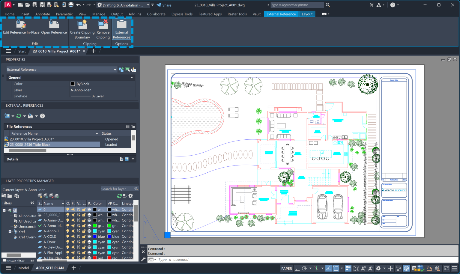
There are two primary ways to create a title block in AutoCAD: you can create a block with attributes that can be adapted depending on the sheet or create a .dwg file that will be used as an XREF (external reference) in your drawings. I’ll cover both in this tutorial and go into more detail on how to create a block, using each method, in step 4.
The next step is to plan out what information your title block should have. Some common elements include:
Once you have a clear idea of what information you want to include in your title block, it’s time to set up your layout. This involves creating a template with the correct paper size, border, and title block placement. You can either create a new template from scratch or use an existing one and make modifications as needed.
Now it’s time to start creating your title block using the tools in AutoCAD. Some tips to keep in mind here include:
To create a title block as an XREF, you can follow these steps:
To create a title block with attributes, you can follow these steps:
The final step is to insert your newly created title block into your drawing. To do this, you can use the “Insert” command or the XREF method I mentioned earlier. If you choose to use an XREF, remember to make any changes in the source file and update the XREF in your drawing to reflect those changes.
Congratulations! you now know how to create a title block in AutoCAD using both methods. Remember to plan what information you want to include, set up your layout, and use layers and blocks for easier management. With these steps, you can easily create professional-looking title blocks for all your AutoCAD drawings.
Now that you know how to create a title block in AutoCAD, let’s explore how you can customize it further. Here are some tips for making your title block stand out and reflect your unique style or company branding:
Incorporating design elements in AutoCAD title blocks is essential for several reasons:
To ensure a smooth and efficient workflow when using title blocks in AutoCAD, here are some best practices to keep in mind:
By following these best practices, you can effectively manage your title blocks in AutoCAD and save time in the long run.
Title blocks are essential in any technical drawing, and learning how to create and customize them in AutoCAD can significantly streamline your workflow. Following the steps outlined in this guide, you can easily create professional-looking title blocks that will help identify and organize your drawings while reflecting your unique style or company branding. Incorporating design elements, using best practices for management, and regularly updating your title block will ensure consistency and efficiency in all your AutoCAD projects.

Features the latest informative and technical content provided by our industry experts for designers, engineers, and construction firms and facility owners.
LEARN MORESTAY IN TOUCH
