As of April 30, 2025, we’re proud to announce our exciting new chapter. | Read more here.
Sustainable design has become a cornerstone of modern architecture and urban planning, emphasizing resource efficiency, environmental responsibility, and long-term resilience. As the construction industry faces increasing pressure to reduce carbon footprints and optimize energy performance, digital tools like Autodesk Forma are revolutionizing the way architects and engineers approach sustainability.
By leveraging data-driven insights and predictive modeling, Autodesk Forma enables professionals to design buildings that minimize environmental impact while maximizing efficiency and functionality.
This article explores the role of Autodesk Forma in promoting sustainable design, its benefits, and the challenges it helps overcome in the pursuit of greener, more efficient buildings.
Sustainable design focuses on reducing resource consumption, minimizing waste, and creating buildings that enhance human well-being while mitigating their impact on the planet. Because buildings account for nearly 40% of global energy consumption and 30% of greenhouse gas emissions, it is no wonder why sustainability in building design is of paramount importance. Key aspects of sustainable design include energy efficiency, water conservation, material sustainability, and indoor environmental quality.
As sustainability becomes a global priority, digital tools like Autodesk Forma are playing a pivotal role in enabling teams of architects and engineers to integrate sustainable principles into their designs from the earliest stages. By utilizing advanced simulations and real-time data, these tools can empower your team to make informed decisions that align with sustainability goals.
Autodesk Forma is a powerful cloud-based design tool that integrates sustainability analysis into the early stages of architectural planning. With AI tools and real-time environmental data, Forma enables architects, urban planners, and engineers to make data-driven decisions that optimize energy efficiency, reduce carbon footprints, and enhance overall building performance.
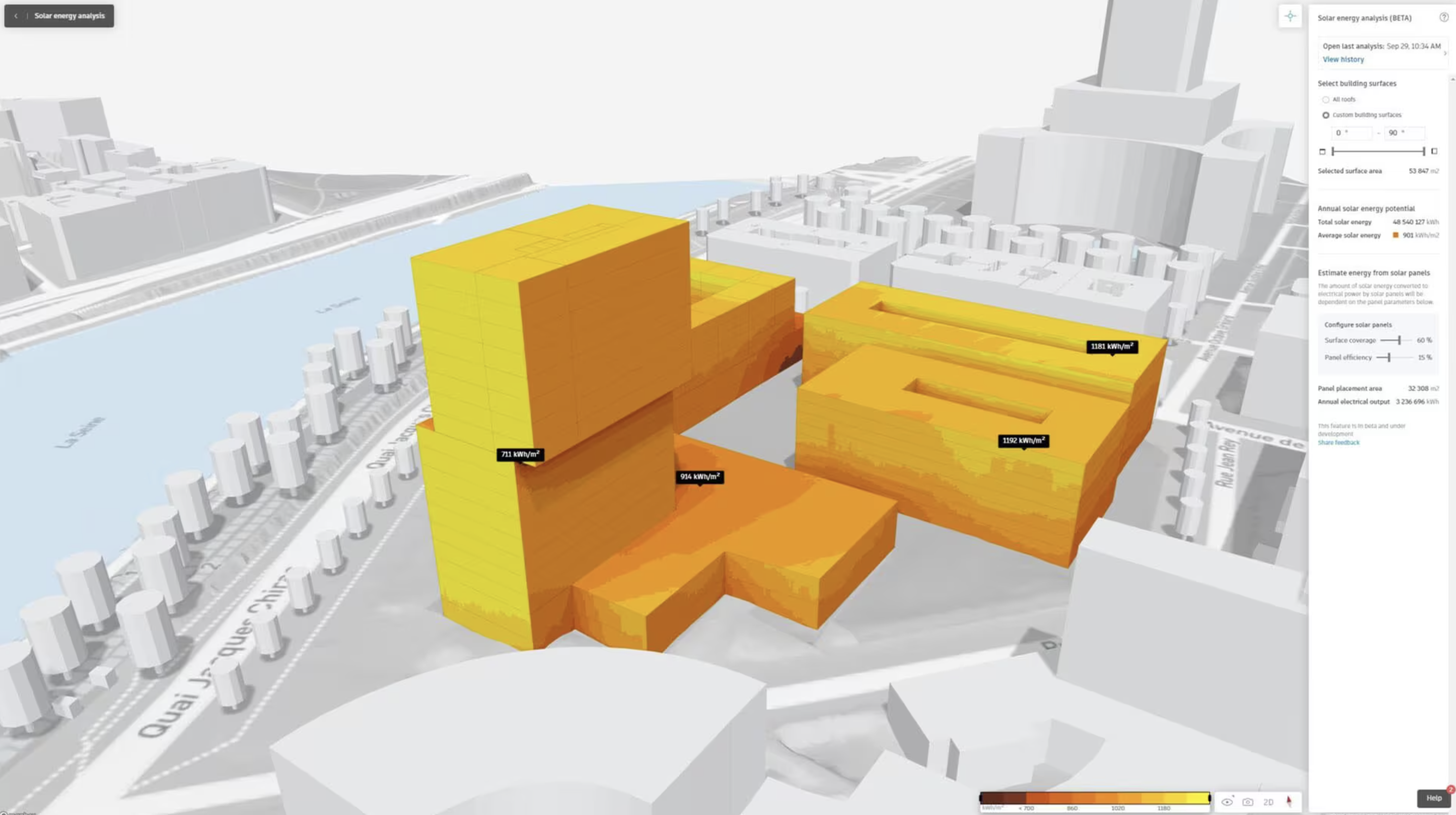
One of Forma’s key strengths is its ability to analyze site-specific conditions such as sunlight exposure, wind flow, and energy consumption patterns. These insights allow designers to adjust building orientations, facade designs, and material selections to maximize sustainability.
For example, Forma can simulate how different design choices impact daylight utilization and solar heat gain, helping architects optimize passive heating and cooling strategies. Additionally, Forma supports carbon impact assessments, allowing users to evaluate and reduce the embodied carbon of materials and construction processes. This feature is crucial as the industry shifts toward net-zero energy and carbon-neutral buildings.
Incorporating Autodesk Forma into the design process offers numerous benefits that enhance both environmental sustainability and project efficiency. By providing real-time data analysis and predictive simulations, Forma can help your cross-functional teams make informed decisions that lead to more sustainable outcomes.
Forma enables designers to assess solar exposure, wind patterns, and thermal performance, allowing them to optimize building orientation, glazing, and shading strategies to reduce energy consumption.
With real-time simulations and AI-driven analysis, Forma allows professionals to test multiple design scenarios and select the most sustainable option. This reduces guesswork and ensures that buildings meet energy performance and sustainability benchmarks.
Forma helps designers evaluate the embodied carbon of materials and explore low-impact alternatives, contributing to the creation of carbon-neutral structures. By integrating lifecycle analysis early in the process, projects can reduce long-term environmental effects.
Autodesk Forma provides insights into rainwater management, green infrastructure, and passive design strategies, helping architects incorporate features like green roofs, permeable surfaces, and efficient water systems.
Forma simplifies the process of meeting sustainability standards such as LEED, BREEAM, and WELL certifications. This ensures designs remain compliant with different sustainability standards.
Sustainable design is guided by a set of core principles that prioritize environmental responsibility, resource efficiency, and occupant well-being. By incorporating these principles into the design process, architects and engineers can create buildings that minimize negative environmental impacts while maximizing long-term benefits.
A key strategy in sustainable design is optimizing energy use through passive design techniques. This includes maximizing natural daylight, optimizing building orientation, and leveraging thermal mass to reduce reliance on artificial heating and cooling. Autodesk Forma helps designers simulate these factors, ensuring that buildings achieve optimal energy performance from the start.
Selecting low-impact, locally sourced, and recyclable materials is essential for reducing a building’s embodied carbon. Forma’s carbon impact assessment tools allow designers to evaluate materials based on their environmental footprint, helping them choose options that align with sustainability goals.
Sustainable design incorporates rainwater harvesting, efficient plumbing fixtures, and drought-resistant landscaping to minimize water waste. Forma provides climate and site analysis data, enabling architects to integrate water-efficient solutions tailored to specific geographic conditions.
With climate change increasing the frequency of extreme weather events, buildings must be designed to withstand environmental stresses. Forma’s climate analysis capabilities help professionals assess factors such as flood risks, wind loads, and temperature variations, allowing them to develop resilient, adaptable structures.
Sustainable buildings enhance occupant well-being by incorporating green roofs, vertical gardens, and outdoor communal spaces. These features improve air quality, regulate temperatures, and contribute to urban biodiversity. Forma’s urban analysis tools support the planning of these elements, ensuring they are integrated effectively.
Sustainable buildings aim to reduce environmental impact and enhance efficiency. Autodesk Forma supports this by optimizing energy use through strategies like solar orientation and passive cooling. It helps select low-carbon materials and improve indoor air quality by simulating natural lighting and ventilation.
Forma also facilitates water efficiency and the integration of renewable energy sources like solar panels, ensuring buildings are both eco-friendly and resilient. Additionally, Forma streamlines the incorporation of smart technologies, making buildings future-ready and energy-efficient.
The characteristics outlined above can be seen in examples of sustainable architecture all over the world. With green architecture gaining popularity as countries such as the United States attempt to reach its net-zero emissions goal by 2050.
Sustainable design faces several challenges, including high initial costs, complex regulations, late-stage sustainability integration, and industry resistance to change. Many stakeholders hesitate due to the upfront expenses of eco-friendly materials and renewable systems, even though these investments lead to long-term savings. Additionally, meeting sustainability standards like LEED and BREEAM requires extensive data tracking, and many projects struggle with accurately predicting energy performance and carbon impact.
Autodesk Forma helps overcome these barriers by integrating sustainability analysis from the conceptual stage, allowing designers to optimize energy efficiency, material selection, and carbon impact early in the process. Its AI-driven simulations and real-time performance metrics simplify compliance with regulations and provide cost-benefit analyses to justify sustainable investments.
Additionally, Forma’s user-friendly interface and integration with Autodesk’s ecosystem make it easier for firms to adopt sustainable practices without disrupting existing workflows. By addressing these challenges, Forma empowers architects and engineers to create sustainable, cost-effective, and high-performance buildings.
Autodesk Forma is transforming sustainable design by enabling data-driven decisions that optimize energy efficiency, reduce environmental impact, and enhance building performance.
As the industry continues to prioritize sustainability, tools like Forma will play a crucial role in shaping the future of architecture, making it easier for professionals to create buildings that are not only environmentally responsible but also cost-effective and resilient. With ongoing advancements in AI and real-time analytics, the future of sustainable design looks promising, with greater integration of technology to meet global sustainability goals.
Microsol Resources. (n.d.). Autodesk Forma. Retrieved March 17, 2025, from https://microsolresources.com/software/autodesk/autodesk-forma/
Microsol Resources. (n.d.). What is Autodesk Forma & why is it important to the AEC workflow? Retrieved March 17, 2025, from https://microsolresources.com/tech-resources/article/what-is-autodesk-forma-why-is-it-important-to-the-aec-workflow/
Microsol Resources. (n.d.). Enscape impact: Real-time insights for sustainable design. Retrieved March 17, 2025, from https://microsolresources.com/tech-resources/article/enscape-impact-real-time-insights-for-sustainable-design/
Microsol Resources. (n.d.). 7 examples of green architecture around the world. Retrieved March 17, 2025, from https://microsolresources.com/tech-resources/article/7-examples-of-green-architecture-around-the-world/
Farrelly, L. (2023, October 4). What is sustainable architecture? In The Spruce. Retrieved March 17, 2025, from https://www.thespruce.com/what-is-sustainable-architecture-4846497
In today’s construction landscape, managing vast amounts of project documentation, from design files and RFIs to submittals and compliance records, has become increasingly complex. Disorganized or inaccessible data can delay timelines, inflate budgets, and compromise quality.
Autodesk Docs is a cloud-based document management solution within the Autodesk Construction Cloud that is designed to tackle these challenges head-on. This article provides a comprehensive overview of Autodesk Docs, exploring how it can streamline your document control, enhance collaboration, and support construction teams in delivering their best work.
Autodesk Docs is a centralized document management solution that serves as the common data environment (CDE) within the Autodesk Construction Cloud ecosystem. It provides a structured, secure platform to manage, organize, and distribute project documentation across all phases. By offering a single source for drawings, models, and files, Autodesk Docs minimizes the risk of errors caused by outdated or miscommunicated information.
In the context of construction, Autodesk Docs plays a pivotal role in improving collaboration between architects, engineers, contractors, and project owners. Your teams can easily access the latest project documents from any device, track revisions in real time, and maintain version control without the confusion of email threads or other storage systems. Finally, the software’s integration with other Autodesk tools such as Revit, AutoCAD, and BIM Collaborate ensures seamless workflows.
Autodesk Docs comes equipped with several features that address the common pain points you and your construction team members likely face today regarding document management.
Autodesk Docs provides a single, cloud-based repository where all project documents are stored and organized. This centralization eliminates the need for disconnected storage systems or manual document distribution. Users can organize files using customizable folder structures, enforce permission settings, and ensure all stakeholders are accessing the same information, reducing the risk of miscommunication.
One of the most critical aspects of document management in construction is ensuring that team members are working with the latest version of a file. Autodesk Docs automatically tracks file versions, maintaining a complete history of changes and edits. Your users can easily compare versions, see who made specific updates, and revert to earlier iterations if necessary. This robust version control system helps avoid costly rework caused by outdated documents being used in the field.
Autodesk Docs supports real-time collaboration by enabling multiple stakeholders to view, comment on, and mark up documents simultaneously. The built-in viewer supports 2D drawings and 3D models without requiring external software. This feature makes it easier for teams to engage with complex project data. Comments and markups are linked to specific files and retained throughout the project lifecycle, fostering a more cohesive communication stream.
Implementing Autodesk Docs in a construction project offers tangible benefits across collaboration, compliance, and operational performance. By standardizing how documents are managed and accessed, teams can avoid common pitfalls that delay timelines and drive up costs.
Autodesk Docs enables teams to collaborate more effectively by providing a shared platform where all stakeholders can access up-to-date project information in real time. Instead of relying on fragmented communication methods or separate document repositories, your multi-disciplinary teams can view, comment, and mark up files in one convenient location.
With robust permission settings, approval workflows, and audit trails, Autodesk Docs helps teams maintain control over sensitive documentation and ensure compliance with industry standards. Administrators can set access levels by user role or folder, ensuring only the right people can view or modify certain files.
Automated workflows for reviews and approvals reduce manual errors, while built-in tracking features provide a verifiable record of who accessed or edited a document, which can be key for regulatory compliance and quality assurance.
Autodesk Docs gives project managers and stakeholders real-time visibility into the status of documents, reviews, and approvals. This level of transparency helps identify bottlenecks early, streamline handoffs between teams, and reduce downtime caused by information gaps. Because all documents are connected to a unified data environment, Autodesk Docs also supports data continuity across other Autodesk Construction Cloud tools. This helps your teams make more informed decisions and deliver projects more efficiently.
The process typically begins with setting up a project in Autodesk Construction Cloud, where administrators can define folder structures, assign permissions, and configure workflows tailored to the project’s needs. Project files (2D drawings, 3D models, photos, PDFs, etc.) are then uploaded into the system. From there, users can collaborate directly within the platform by reviewing documents, adding markups, submitting RFIs, or initiating approval workflows.
As previously mentioned, Autodesk Docs also supports integration with design tools like Revit and AutoCAD, enabling seamless transitions from design to construction. As changes are made to drawings or models, updated files can be published directly to Docs, which maintains version control and keeps your field teams aligned with the latest revisions.
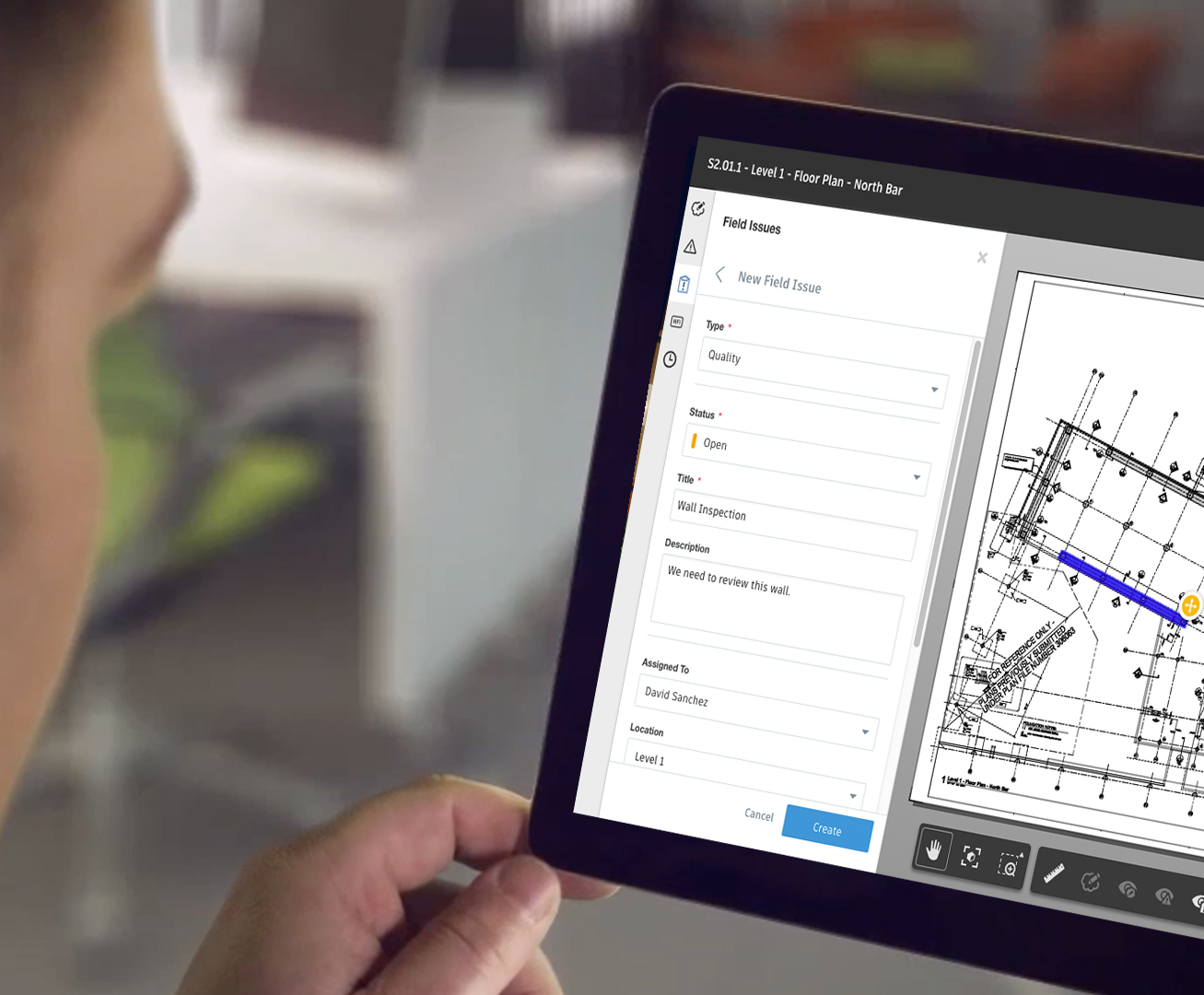
On the job site, field personnel can access project files via tablets or mobile devices using the Autodesk Build app, ensuring that critical documents are available anytime, even offline. This improves responsiveness to changes, reduces reliance on printed drawings, and supports faster issue resolution.
By embedding document management into every stage of a project, Autodesk Docs helps construction teams maintain data integrity and subsequently deliver higher quality results.
Autodesk Docs supports several core workflows critical to construction teams. Below, you will find some of the most common applications in day-to-day project work:
Teams on the job site use Autodesk Docs to access the latest drawings and models directly from mobile devices, ensuring everyone works from the same version. Real-time markups and issue tracking help resolve problems quickly and keep field activities aligned with project plans.
Autodesk Docs streamlines submittal and RFI workflows by centralizing submissions, approvals, and document tracking. Custom workflows and audit trails further enhance accountability and maintain compliance.
Design teams can securely share 2D drawings and 3D models with stakeholders, who can view and comment on files without needing additional software. This simplifies communication between multi-disciplinary teams and enhances clarity.
While Autodesk Docs offers powerful document management capabilities, there are a few considerations to keep in mind. First, teams unfamiliar with Autodesk’s interface may face a learning curve, particularly when integrating Docs with other tools like BIM Collaborate or Revit.
Additionally, although the platform supports a wide range of file types, users may experience limitations when working with non-Autodesk formats or highly customized workflows that require third-party integrations.
Another factor to consider is cost. While Autodesk Docs is included in the Autodesk Construction Cloud, accessing its full potential often requires a broader investment in the platform’s suite of tools.
Lastly, like any cloud-based system, consistent internet connectivity is essential for accessing and syncing the latest files, which may pose challenges on remote or infrastructure-limited job sites.
Despite these considerations, Autodesk Docs remains a robust solution when implemented thoughtfully within a well-supported digital workflow.
Implementing Autodesk Docs is a straightforward process, but thoughtful setup and user onboarding can make a big difference in how smoothly your team adopts the platform.
To get started, project administrators create a new project within the Autodesk Construction Cloud platform and configure Autodesk Docs as a service. From there, they can invite users, assign roles, and define permissions based on responsibilities. Note, it will be important to provide early onboarding (training, tutorials, informational touchpoints, etc.) to all relevant parties.
A clear folder structure is essential for keeping documents organized and accessible. Consider setting up folders by discipline, phase, or workflow (e.g., “Design,” “Construction Docs,” “Submittals”). Standardized file naming conventions, such as including project codes, dates, or version numbers, help reduce confusion and ensure version clarity across the team.
New users should take advantage of the platform’s built-in viewer and markup tools to get comfortable with reviewing and commenting on documents. It’s also helpful to set document permissions carefully from the start to avoid accidental edits or visibility issues. Finally, encourage users to use the mobile app in the field. Offline access and real-time updates are key to keeping field and office teams in sync.
Autodesk Docs plays a critical role in modern construction by centralizing document management It improves collaboration, and streamlines project workflows. When implemented thoughtfully, it will enhance visibility, reduce errors, and aid your teams in delivering the highest quality of work.
Microsol Resources. (n.d.-d). Autodesk Docs software. https://microsolresources.com/software/autodesk/autodesk-docs/
Microsol Resources. (n.d.-e). What’s new with Autodesk 2026? https://microsolresources.com/tech-resources/article/whats-new-with-autodesk-2026
Microsol Resources. (n.d.-f). BIM 360 Docs essentials training. https://microsolresources.com/training/autodesk/bim-360-docs-essentials/
Sunlight and wind play a crucial role in architectural design, influencing everything from energy efficiency to occupant comfort. Thoughtful consideration of these natural elements can reduce reliance on artificial lighting, heating, and cooling, ultimately leading to more sustainable buildings.
Architects and designers leverage sunlight and wind analysis to optimize building orientation, facade design, and ventilation strategies, ensuring structures harmonize with their environment. By integrating these factors early in the design process, professionals can create spaces that are not only functional but also resilient and energy efficient. In this article we will review sunlight and wind analysis specifically through the use of tools in Autodesk Forma.
Environmental analysis in architecture involves evaluating natural factors such as sunlight, wind patterns, temperature, and humidity to inform design decisions. By analyzing site-specific conditions, designers can optimize building orientation, window placement, and ventilation strategies to reduce energy consumption and improve occupant well-being. Modern CAD tools (Forma) and simulation software (building information modeling – BIM) further refine this analysis, allowing architects to test different design scenarios and make data-driven decisions for optimal performance.
Wind analysis is essential in architecture, influencing energy efficiency, structural stability, and occupant comfort. Poorly managed wind conditions can create safety hazards, increase heat loss, or cause discomfort in outdoor spaces. Architects use wind analysis to optimize natural ventilation, reduce reliance on mechanical cooling, and design aerodynamic structures that minimize wind resistance. In urban settings, strategic building placement can prevent wind tunnels, while in high-wind areas, windbreaks like trees or barriers help improve comfort. By integrating wind analysis early, architects ensure buildings are both resilient and environmentally efficient.
From the above section, you can see where wind analysis can be useful in architecture. To further emphasize, a case study in wind analysis using Forma can be seen in The Marina Bay Sands Resort in Singapore. Situated in a tropical climate, the development required careful wind studies to balance natural ventilation with structural stability. Wind engineering firm CPP, Inc. conducted extensive wind tunnel testing on scaled models of the property to assess both normal and extreme wind conditions and their effects on the SkyPark. This analysis informed the design of an effective supplemental damper system, reducing motion and enhancing occupant comfort.
Autodesk Forma uses real-time environmental analysis features that allow you and your team to assess wind speed, pressure distribution, and airflow patterns around buildings and urban landscapes. By integrating CFD (Computational Fluid Dynamics) principles, Forma helps architects visualize how wind interacts with built environments, identifying potential problem areas such as high-pressure zones or wind tunnels. Designers can use this data to refine building shapes, adjust orientations, or incorporate ventilation strategies that enhance comfort and energy efficiency.
Forma helps architects develop wind-responsive design strategies by identifying pressure zones and airflow patterns early in the design process. In high-rise buildings, Forma can guide your architects to proper placement of setbacks or voids to reduce wind turbulence, while perforated facades and wind baffles can help control airflow. Urban planners also use Forma to assess pedestrian wind comfort, optimizing street layouts, building heights, and landscaping elements like trees or windbreaks to create more walkable environments. Incorporating these design considerations for wind analysis using Forma elevates the final product to new heights.
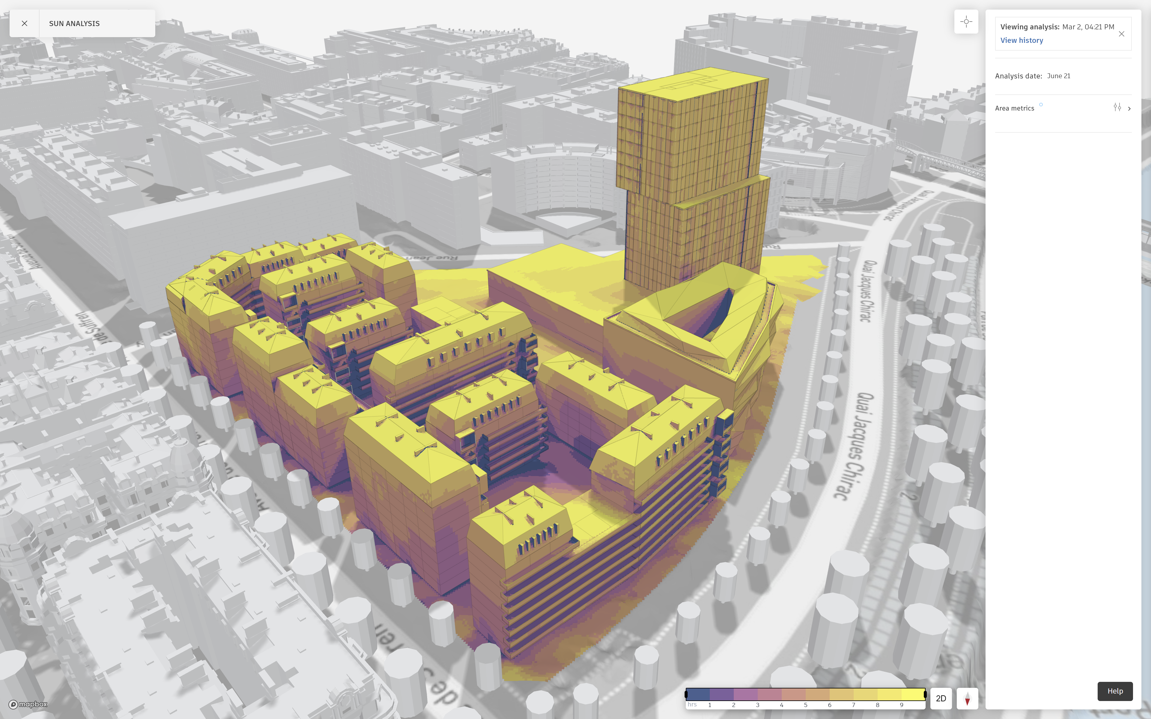
Effective sunlight analysis is essential for optimizing building performance, energy efficiency, and occupant comfort. Autodesk Forma provides architects with powerful tools to assess solar exposure, shadow patterns, and daylight penetration throughout different seasons.
Sunlight analysis is critical in several sectors of design. Proper daylighting reduces reliance on artificial lighting, lowering energy costs and enhancing sustainability. Sun exposure also affects thermal comfort, requiring architects to balance natural light intake with shading strategies to prevent overheating or glare. Additionally, sunlight plays a vital role in urban planning, impacting factors like shadowing on neighboring buildings and public spaces.
Gund Hall, the main building of the Harvard Graduate School of Design, underwent a daylighting study to enhance its interior lighting conditions. Lam Partners collaborated with Bruner/Cott Architects and Vanderweil Engineers to analyze the building’s “trays” (tiered studio spaces). Through comprehensive daylighting studies, the team developed design solutions that improved natural light distribution, enhancing the functionality and comfort of the studio spaces.
Autodesk Forma offers powerful tools for evaluating solar exposure, shadow impact, and daylight distribution throughout a building’s design. Its real-time solar analysis allows architects to assess how sunlight interacts with structures across different times of the day and seasons. Additionally, its daylighting analysis enables precise placement of windows, skylights, and shading devices to balance natural light and energy efficiency.
Autodesk Forma offers solar mapping, shadow analysis, and daylight simulations to optimize building performance. Its tools help architects refine orientation, assess shading impacts, and adjust glazing or materials for better daylight distribution. By leveraging these techniques, designers can enhance energy efficiency, sustainability, and occupant comfort.
Autodesk Forma helps architects evaluate how materials interact with sunlight to optimize energy efficiency and comfort. Its analysis tools assess factors like solar reflectance, heat absorption, and glare, guiding material choices for facades, roofing, and glazing. Designers can test different materials to reduce heat gain, enhance daylight distribution, and improve thermal performance.
While wind and sunlight analysis are essential for creating energy-efficient and comfortable buildings, several challenges can arise during the process. One challenge is accurately predicting environmental factors in complex urban settings, where surrounding buildings and topography can significantly influence wind patterns and sunlight exposure. Variability in weather conditions, seasonal changes, and the unpredictable nature of climate also complicate precise forecasting. Additionally, integrating these analyses with other design considerations, such as structural integrity or aesthetic preferences, can create design conflicts. Overcoming these challenges requires advanced simulation tools, iterative testing, and collaboration between architects, engineers, and environmental consultants to ensure that both wind and sunlight are effectively managed in the final design.
Wind and sunlight analysis are crucial for creating energy-efficient, comfortable buildings. Tools like Autodesk Forma enable architects to make informed design decisions that optimize environmental conditions and reduce energy use. While challenges remain, advancements in simulation technology and the integration of AI will improve the accuracy and adaptability of these analyses. As sustainability becomes a priority, the role of environmental analysis in architecture will continue to grow, fostering more resilient and eco-friendly buildings.
Microsol Resources. (n.d.). What is Autodesk Forma and why is it important to the AEC workflow? Retrieved March 17, 2025, from https://microsolresources.com/tech-resources/article/what-is-autodesk-forma-why-is-it-important-to-the-aec-workflow/
Microsol Resources. (n.d.). Autodesk Forma. Retrieved March 17, 2025, from https://microsolresources.com/software/autodesk/autodesk-forma/
CPP Wind. (n.d.). Understanding wind effects on ground-breaking architecture. Retrieved March 17, 2025, from https://cppwind.com/portfolios/understanding-wind-effects-on-ground-breaking-architecture/
Lam Partners. (n.d.). Sunlighting the trays: Gund Hall daylighting case study. Retrieved March 17, 2025, from https://www.lampartners.com/case-studies/sunlighting-the-trays-gund-hall-daylighting-case-study/

Features the latest informative and technical content provided by our industry experts for designers, engineers, and construction firms and facility owners.
LEARN MORESTAY IN TOUCH
