Microsol Resources, a leading provider of technology solutions for architecture, engineering, and construction (AEC) firms, is proud to announce that it will join its parent company, Graitec Group, at Autodesk University (AU) 2025 in Nashville, TN, from September 16–18, 2025.
This year’s conference theme, The New Era of Making, will highlight the latest advancements in AI, data-driven decision-making, sustainable practices, and achieving more with less. As a Diamond Sponsor of AU 2025, Graitec will showcase the power of innovation and implementation on the show floor—bringing the future of BIM, automation, and project delivery to life.
The event also marks an important milestone for Microsol Resources, following its recent acquisition by Graitec Group.
Exclusive Discount Offer
Register through Graitec for a special discounted rate of $1,799 (regularly $2,250). Request your discount code today and email microsolinfo@graitec.com!
Visit Us at Booth #220
Attendees can connect with Microsol Resources and Graitec experts at Booth #220 in the Expo Hall to explore:
Live Demos: See how Graitec solutions supercharge Autodesk workflows—from design to fabrication and beyond.
Tech Talks: Gain practical tips for both long-standing customers and new users.
Innovative Tools: Experience solutions spanning Autodesk software integrations, Ideate Software, Strucsoft, Advance Design, File Sync, and more.
Prizes & Giveaways: Enter for a chance to win Meta Glasses, a custom cowboy hat, cowboy boots, and other exciting prizes.
Presentations: Check out the various sessions led by Graitec’s thought leaders, including Manuel Liedot, CEO of Graitec, and other industry experts.
VIP Party: BIM & Boots
Don’t miss Graitec’s exclusive VIP Party: BIM & Boots, an evening of networking, entertainment, and Nashville flair.
Date: Wednesday, September 17, 2025
Time: 6:30–9:30 PM
Location: Nashville Live! (just steps away from Music City Center) Expect live country music, line dancing, games, an open bar, great food—and yes, even mechanical bull riding.
Sunlight and wind play a crucial role in architectural design, influencing everything from energy efficiency to occupant comfort. Thoughtful consideration of these natural elements can reduce reliance on artificial lighting, heating, and cooling, ultimately leading to more sustainable buildings.
Architects and designers leverage sunlight and wind analysis to optimize building orientation, facade design, and ventilation strategies, ensuring structures harmonize with their environment. By integrating these factors early in the design process, professionals can create spaces that are not only functional but also resilient and energy efficient. In this article we will review sunlight and wind analysis specifically through the use of tools in Autodesk Forma.
Understanding Environmental Analysis in Architecture
Environmental analysis in architecture involves evaluating natural factors such as sunlight, wind patterns, temperature, and humidity to inform design decisions. By analyzing site-specific conditions, designers can optimize building orientation, window placement, and ventilation strategies to reduce energy consumption and improve occupant well-being. Modern CAD tools (Forma) and simulation software (building information modeling – BIM) further refine this analysis, allowing architects to test different design scenarios and make data-driven decisions for optimal performance.
Wind Analysis with Autodesk Forma
Importance of Wind Analysis in Architecture
Wind analysis is essential in architecture, influencing energy efficiency, structural stability, and occupant comfort. Poorly managed wind conditions can create safety hazards, increase heat loss, or cause discomfort in outdoor spaces. Architects use wind analysis to optimize natural ventilation, reduce reliance on mechanical cooling, and design aerodynamic structures that minimize wind resistance. In urban settings, strategic building placement can prevent wind tunnels, while in high-wind areas, windbreaks like trees or barriers help improve comfort. By integrating wind analysis early, architects ensure buildings are both resilient and environmentally efficient.
Analyzing Wind Patterns and Effects with Autodesk Forma
From the above section, you can see where wind analysis can be useful in architecture. To further emphasize, a case study in wind analysis using Forma can be seen in The Marina Bay Sands Resort in Singapore. Situated in a tropical climate, the development required careful wind studies to balance natural ventilation with structural stability. Wind engineering firm CPP, Inc. conducted extensive wind tunnel testing on scaled models of the property to assess both normal and extreme wind conditions and their effects on the SkyPark. This analysis informed the design of an effective supplemental damper system, reducing motion and enhancing occupant comfort.
Tools and Techniques in Autodesk Forma for Wind Analysis
Autodesk Forma uses real-time environmental analysis features that allow you and your team to assess wind speed, pressure distribution, and airflow patterns around buildings and urban landscapes. By integrating CFD (Computational Fluid Dynamics) principles, Forma helps architects visualize how wind interacts with built environments, identifying potential problem areas such as high-pressure zones or wind tunnels. Designers can use this data to refine building shapes, adjust orientations, or incorporate ventilation strategies that enhance comfort and energy efficiency.
Design Strategies for Wind Challenges Using Forma
Forma helps architects develop wind-responsive design strategies by identifying pressure zones and airflow patterns early in the design process. In high-rise buildings, Forma can guide your architects to proper placement of setbacks or voids to reduce wind turbulence, while perforated facades and wind baffles can help control airflow. Urban planners also use Forma to assess pedestrian wind comfort, optimizing street layouts, building heights, and landscaping elements like trees or windbreaks to create more walkable environments. Incorporating these design considerations for wind analysis using Forma elevates the final product to new heights.
Sunlight Analysis with Autodesk Forma
Effective sunlight analysis is essential for optimizing building performance, energy efficiency, and occupant comfort. Autodesk Forma provides architects with powerful tools to assess solar exposure, shadow patterns, and daylight penetration throughout different seasons.
Importance of Sunlight Analysis in Architectural Design
Sunlight analysis is critical in several sectors of design. Proper daylighting reduces reliance on artificial lighting, lowering energy costs and enhancing sustainability. Sun exposure also affects thermal comfort, requiring architects to balance natural light intake with shading strategies to prevent overheating or glare. Additionally, sunlight plays a vital role in urban planning, impacting factors like shadowing on neighboring buildings and public spaces.
Case Study in Design for Optimal Sunlight
Gund Hall, the main building of the Harvard Graduate School of Design, underwent a daylighting study to enhance its interior lighting conditions. Lam Partners collaborated with Bruner/Cott Architects and Vanderweil Engineers to analyze the building’s “trays” (tiered studio spaces). Through comprehensive daylighting studies, the team developed design solutions that improved natural light distribution, enhancing the functionality and comfort of the studio spaces.
Key Sunlight Analysis Features in Autodesk Forma
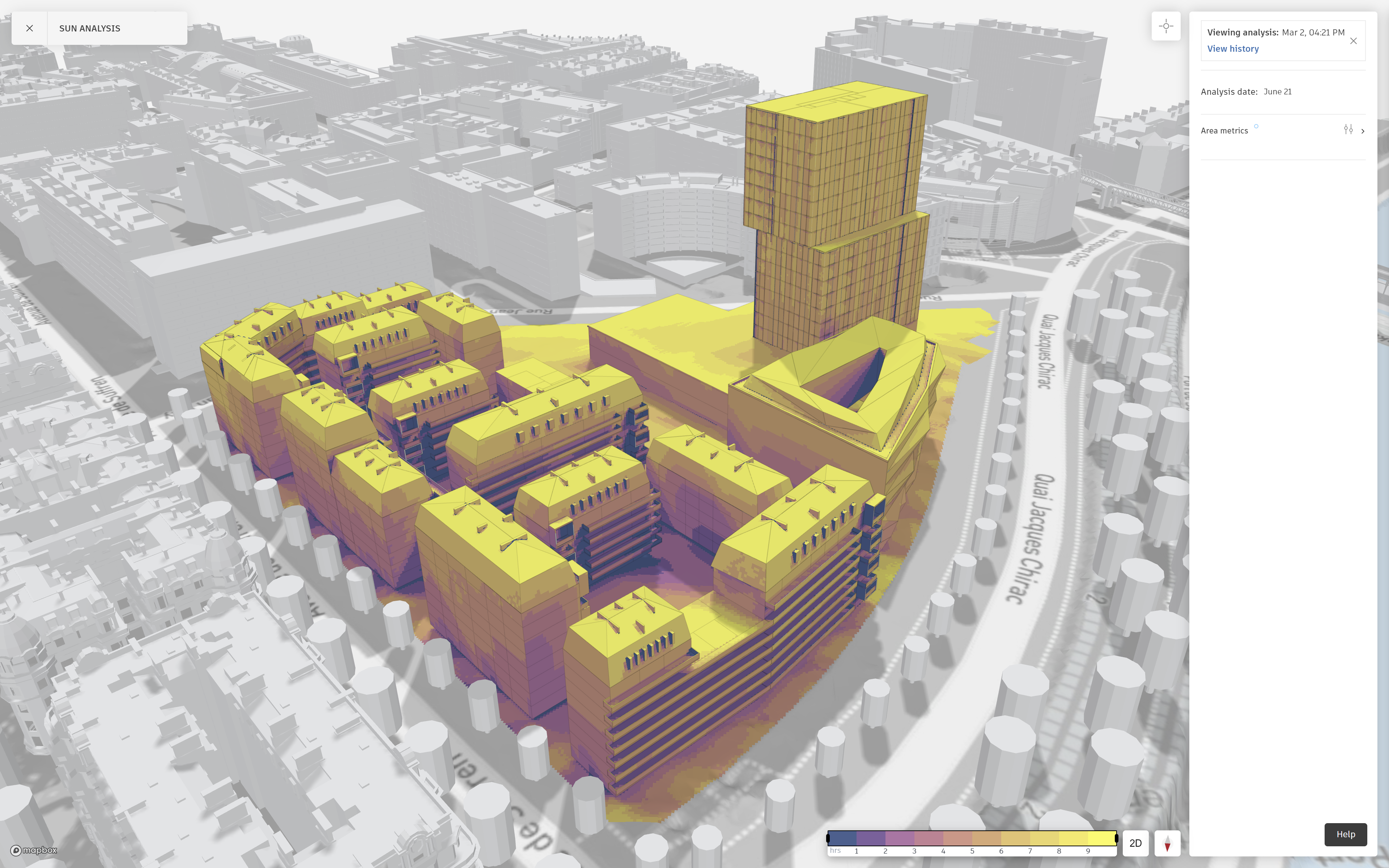
Autodesk Forma offers powerful tools for evaluating solar exposure, shadow impact, and daylight distribution throughout a building’s design. Its real-time solar analysis allows architects to assess how sunlight interacts with structures across different times of the day and seasons. Additionally, its daylighting analysis enables precise placement of windows, skylights, and shading devices to balance natural light and energy efficiency.
Tools and Techniques in Autodesk Forma for Sunlight Analysis
Autodesk Forma offers solar mapping, shadow analysis, and daylight simulations to optimize building performance. Its tools help architects refine orientation, assess shading impacts, and adjust glazing or materials for better daylight distribution. By leveraging these techniques, designers can enhance energy efficiency, sustainability, and occupant comfort.
Material Selection and Solar Impact Using Forma
Autodesk Forma helps architects evaluate how materials interact with sunlight to optimize energy efficiency and comfort. Its analysis tools assess factors like solar reflectance, heat absorption, and glare, guiding material choices for facades, roofing, and glazing. Designers can test different materials to reduce heat gain, enhance daylight distribution, and improve thermal performance.
Challenges in Wind and Sunlight Analysis
While wind and sunlight analysis are essential for creating energy-efficient and comfortable buildings, several challenges can arise during the process. One challenge is accurately predicting environmental factors in complex urban settings, where surrounding buildings and topography can significantly influence wind patterns and sunlight exposure. Variability in weather conditions, seasonal changes, and the unpredictable nature of climate also complicate precise forecasting. Additionally, integrating these analyses with other design considerations, such as structural integrity or aesthetic preferences, can create design conflicts. Overcoming these challenges requires advanced simulation tools, iterative testing, and collaboration between architects, engineers, and environmental consultants to ensure that both wind and sunlight are effectively managed in the final design.
Conclusions and Future Outlook
Wind and sunlight analysis are crucial for creating energy-efficient, comfortable buildings. Tools like Autodesk Forma enable architects to make informed design decisions that optimize environmental conditions and reduce energy use. While challenges remain, advancements in simulation technology and the integration of AI will improve the accuracy and adaptability of these analyses. As sustainability becomes a priority, the role of environmental analysis in architecture will continue to grow, fostering more resilient and eco-friendly buildings.
Predictive analytics is transforming building design by enabling architects and engineers to anticipate performance, optimize efficiency, and reduce costs before construction even begins. By leveraging data-driven insights, designers can make informed decisions about structural integrity, energy efficiency, resource allocation, and overall safety.
Modern CAD tools, such as Autodesk Forma and Building Information Modeling (BIM), integrate predictive analytics to streamline workflows, enhance collaboration, and improve project outcomes. As the construction industry increasingly adopts digital solutions, predictive analytics is becoming a vital component of smarter, more sustainable building design.
What is Predictive Analytics?
Predictive analytics is the process of using historical data, machine learning, and statistical modeling to forecast future outcomes. In building design, it helps architects and engineers anticipate performance issues, optimize resource allocation, and enhance decision-making.
Additionally, advanced integration of BIM and digital twins in facility design allows for real-time tracking of various functions. This is obtained through strategically placed sensors that relay information to relevant stakeholders. By analyzing trends and patterns, predictive analytics enables design teams to proactively address structural, environmental, and operational challenges before they become costly problems.
Importance of Predictive Analytics in Building Design
Predictive analytics plays a critical role in modern building design by enabling data-driven decision-making and risk mitigation. By forecasting potential challenges such as structural weaknesses, energy inefficiencies, and improper resource allocation, designers can refine their plans before construction begins.
Additionally, when integrated into CAD tools, predictive analytics streamlines collaboration between architects, engineers, and contractors, ensuring that projects remain on schedule, on budget, and true to the design’s intent. A real-world example of this integration is with Google’s Bay View Campus in Mountain View, CA. Google leveraged predictive analytics and BIM for the design of its Bay View campus, focusing on sustainability. Advanced simulations helped optimize natural ventilation, daylighting, and thermal comfort, resulting in a highly energy-efficient workspace.
Benefits of Predictive Analytics in Building Design
Predictive analytics brings numerous advantages to building design, helping multidisciplinary teams make informed decisions that enhance efficiency, reduce costs, and improve safety. Let’s take a look at some of the potential benefits in-depth.
Operational Efficiency and Process Optimization with Autodesk Forma
Autodesk Forma, a cloud-based AI-driven tool, leverages predictive analytics to optimize building design workflows. By analyzing multiple design iterations in real time, Forma helps architects and engineers assess energy performance, daylight exposure, and carbon impact before finalizing designs.
Forma’s automation features improve collaboration between stakeholders, fostering alignment in all phases of the project. One of Forma’s key advantages is its ability to automate repetitive tasks, such as zoning and massing studies, allowing designers to focus on refining project details rather than manual adjustments.
A notable example of Forma’s process optimization capabilities can be seen in the design of CopenHill, a waste-to-energy plant in Copenhagen that doubles as a ski slope. The project required extensive energy modeling to balance industrial functionality with environmental sustainability.
Using predictive analytics within BIM and early-stage simulation tools, designers optimized the building’s insulation, ventilation, and energy use. The result was an operationally efficient structure with a 31% reduction in energy consumption compared to traditional waste-to-energy plants.
Resource Allocation and Optimization
Predictive analytics plays a vital role in optimizing resource allocation, ensuring that materials, labor, and time are used efficiently. One key application is Quantity Takeoff, where predictive models analyze historical project data to estimate the exact amount of materials needed for construction. By reducing waste and preventing overordering, these insights lead to significant cost savings.
BIM-integrated predictive analytics further enhances this process by dynamically adjusting material estimates based on design changes, preventing delays and reducing unnecessary expenditures. Furthermore, predictive analytics helps allocate labor efficiently by forecasting workforce requirements, making sure teams are deployed effectively across different phases of the project.
Enhancing Safety and Risk Management
Safety is a critical concern in building design and construction, and predictive analytics helps mitigate risks by identifying potential hazards before they occur. By analyzing past incidents, environmental factors, and structural data, predictive models can highlight areas of concern, such as structural weaknesses or high-risk zones on construction sites.
BIM tools enhance safety planning by simulating different construction scenarios, allowing teams to implement proactive measures that reduce accidents. Finally, predictive analytics assists in monitoring equipment performance, ensuring that critical systems, such as fire suppression and HVAC, are designed with long-term reliability in mind.
Tools and Techniques for Predictive Analytics
BIM and Digital Twin Technology
Building Information Modeling (BIM) and digital twins play a crucial role in predictive analytics by enabling real-time monitoring, simulation, and optimization of building performance. BIM software, such as Autodesk Revit, Graphisoft Archicad, and Bentley Systems’ OpenBuildings, incorporates predictive analytics to assess structural load distribution, energy consumption, and maintenance needs.
Digital twin technology takes this a step further by creating virtual replicas of buildings that continuously collect sensor data on structural integrity, HVAC performance, and occupant behavior. Platforms like Siemens’ MindSphere, Dassault Systèmes’ 3DEXPERIENCE, and IBM Maximo leverage this data for predictive maintenance, reducing operational costs and preventing failures before they occur.
AI-Driven Simulation Tools
AI-powered platforms like Autodesk Forma and Dynamo for Revit use generative design and machine learning algorithms to predict how various design decisions impact energy efficiency, material use, and spatial configurations. These tools allow designers to run multiple simulations in real time, optimizing designs for sustainability and cost-effectiveness.
Data Analytics and Visualization Platforms
Predictive analytics also relies on data processing and visualization tools such as Power BI, Tableau, and Python-based libraries (Pandas, NumPy, and Scikit-learn). These tools help process large datasets, identify trends, and generate insights that inform design decisions, such as climate-responsive building orientation or energy load forecasting.
Computational Fluid Dynamics (CFD) for Environmental Modeling
CFD tools like ANSYS Fluent, Autodesk CFD, and SimScale are crucial for predicting airflow, thermal comfort, and ventilation efficiency in buildings. These simulations allow designers to optimize HVAC system placement and ensure occupant comfort in various environmental conditions.
Barriers to Adoption and How Autodesk Forma Addresses Them
Learning Curve and Resistance to Change
Many professionals hesitate to adopt new AI-driven workflows.
Forma’s Solution: Its intuitive interface, seamless BIM integration, and AI-assisted automation simplify the transition, reducing the need for extensive training.
Data Integration Challenges
Fragmented data across different platforms can disrupt predictive analysis.
Forma’s Solution: It centralizes data and ensures compatibility with BIM models, CAD files, and cloud storage, streamlining collaboration.
Forma’s Solution: As a cloud-based platform, Forma offloads heavy processing to Autodesk’s servers, eliminating the need for expensive hardware.
Cost and ROI Concerns
Firms worry about software costs and uncertain returns on investment.
Forma’s Solution: Its scalable pricing model and efficiency improvements—such as reducing design errors and optimizing resources—help offset costs and increase ROI.
Conclusion
Predictive analytics is transforming building design by enabling data-driven decision-making, improving efficiency, and reducing risks. Tools like Autodesk Forma and BIM-integrated analytics help architects and engineers optimize layouts, resource allocation, and long-term performance.
While adoption challenges exist, advances in AI, cloud computing, and interoperability are making these technologies more accessible. As the AEC industry continues to embrace predictive analytics, firms that integrate these tools will gain a competitive edge, delivering smarter, more sustainable projects.
Features the latest informative and technical content provided by our industry experts for designers, engineers, and construction firms and facility owners.