


Electrical toolset is included with AutoCAD
By Tom Schwarzweller | BIM, CAD
Boost productivity by up to 95% with electrical design features that help you create, modify, and document electrical control systems. With the Electrical toolset, you can access a library of 65,000+ intelligent electrical symbols; automate the numbering of wires and generation of component tags and generate and update multiple customized reports automatically.
Autodesk combined seven industry-specialized toolsets into one version of AutoCAD, and one of those is the Electrical toolset. You can read more about this change here.
Electrical toolset features
65,000+ electrical symbols
Choose from an extensive library of easy-to-use, colorful, and customizable electrical symbols to use in your projects. If an existing symbol doesn’t meet your needs, you can convert symbols or create custom components on the fly using the Symbol Builder tool.
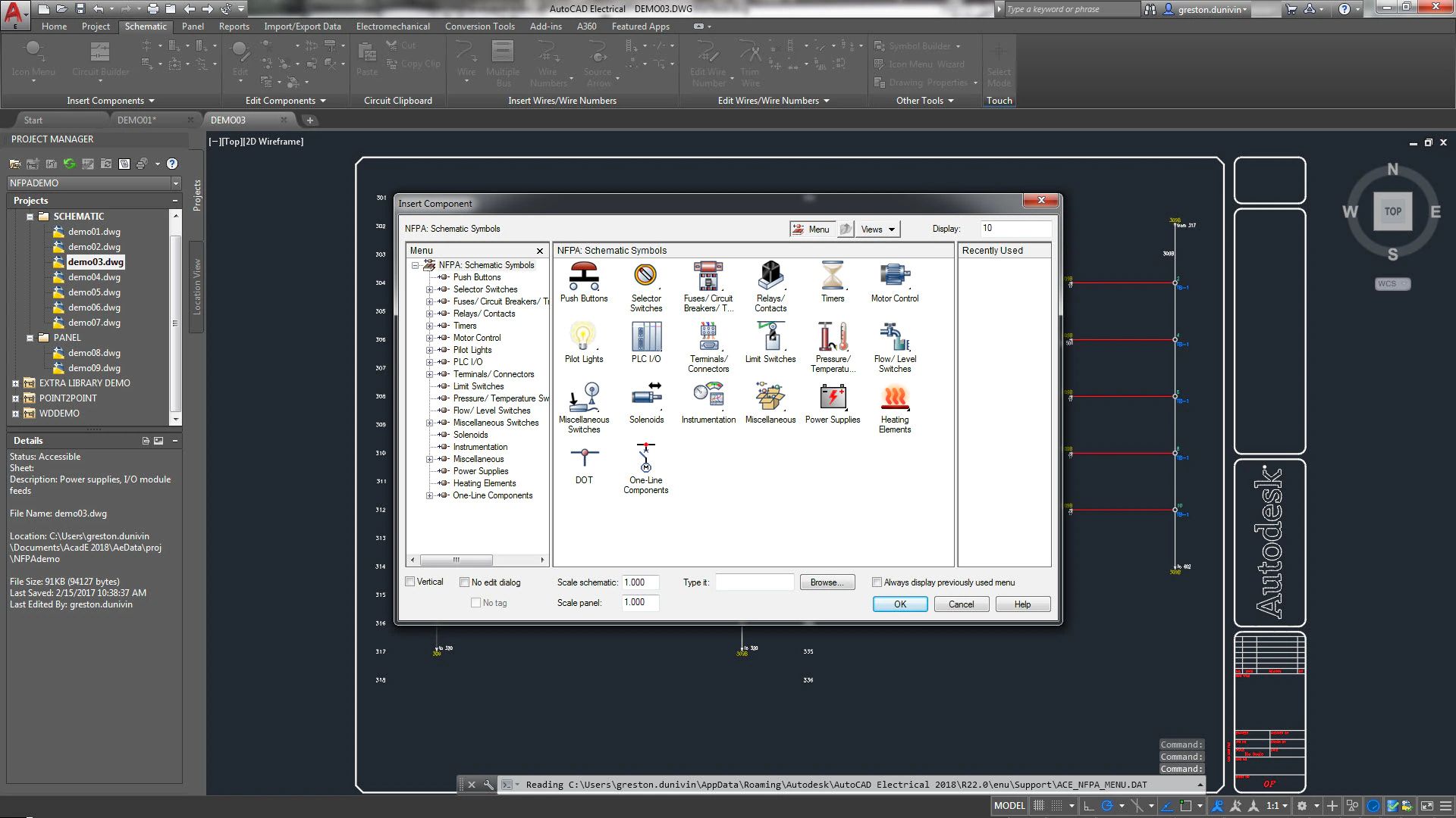
You can convert symbols or create custom components on the fly. Symbols created or converted using Symbol Builder are fully compatible with AutoCAD Electrical toolset. They break wires upon insertion, and appear in the bill of material and various component and wire connection reports.
You can exit the Symbol Builder command and re-enter it at any time. You can also exit the command and use regular AutoCAD commands to edit or finish the symbol you are creating. The AutoCAD Wblock command writes it to disk. Each time you re-enter the Symbol Builder tool, select objects from within the Select Symbol/Objects dialog box. Selecting the objects allows the tool to track what standard attributes and wire connection points you already inserted.
New symbols you create are inserted with the AutoCAD Electrical toolset Insert Component or Insert Panel Component commands. You can add your new symbol to the icon menu. You can also select it from the Type it or Browse options in the bottom left-hand corner of the icon menu. See symbol types below:
Schematic Parent: Schematic symbol is used as a stand-alone symbol or a parent component with related secondary contacts. Must have a TAG1, TAG, or split TAG1 attribute.
Schematic Child: Schematic secondary symbol that is related to a parent component. Must have a TAG2 attribute.
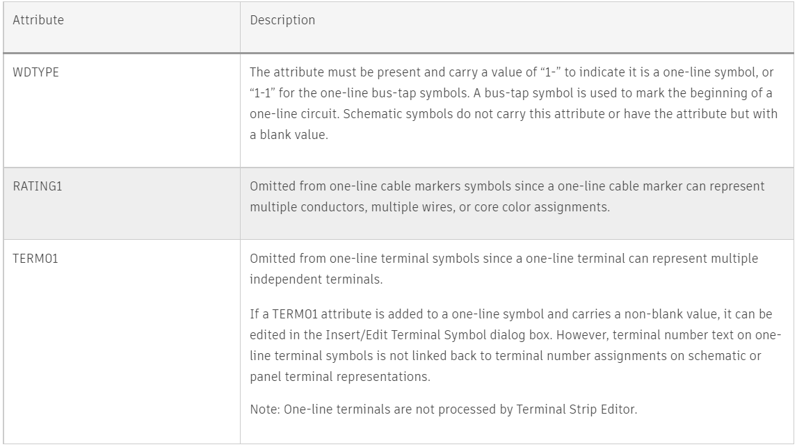
Schematic Terminal: Schematic terminal with terminal number. Must have a TERM01 attribute.
Schematic Terminal: Schematic terminal that follows the wire number rather than having a terminal number of its own. Must have a WIRENO attribute.
Panel Footprint: Panel symbol that is not used as a terminal or nameplate. Must have a P_TAG1 and FP attribute or xdata.
Panel Terminal: Panel terminal symbol. Must have a P_TAGSTRIP and FPT attribute or xdata.
Panel Nameplate: Panel nameplate symbol. Must have a P_TAG1 and NP attribute or xdata.
Note: Panel symbols do not require any attributes but uses xdata for any missing attributes. This xdata is added when the symbol is inserted using the appropriate AutoCAD Electrical toolset panel insertion command. All xdata values have a VIA_WD_ prefix followed by the name of the attribute it takes the place of. For example, if a panel footprint does not have a P_TAG1 attribute it gets a VIA_WD_P_TAG1 xdata when inserted.
Block Editor Environment: Once you make the initial selections, you enter to the Block Editor environment. Your initial selections can include symbol type, attribute template, existing objects, and insertion point. In addition to the Block Editor menus for adding and modifying the symbol graphics, a Symbol builder attribute editor is available for inserting and modifying the AutoCAD Electrical toolset attributes.
Attribute Template: AutoCAD Electrical toolset expects certain attributes for each symbol type, schematic parent, schematic child, and so on. Symbol builder uses attribute templates to facilitate adding these attributes to your symbol. Attribute template drawings are AutoCAD drawings with AutoCAD Electrical toolset attributes. There are different attribute templates for different types of symbols and for different family codes. The supplied attribute templates are in the symbol library folders and all attribute template drawing names begin with “AT_”.
When you select your symbol type, the associated attribute template is used to create a list of attributes. The attribute template can contain attributes defined as required and others as optional. The required attributes are expected on the specific symbol type you are building. Optional attributes are attributes that may not be necessary on this symbol type but are supported. For example rating or switching position attributes. You can insert the attributes individually as needed, or you can insert all the attributes from the template at one time.
Attribute templates follow the naming convention, AT_{symbol}_{type}. The {symbol} string is displayed in the Symbol list in the Select Symbol/Objects dialog box and the {type} string is displayed in the Type list. You can also map abbreviations for the {type} in the _FAMILY_DESCRIPTION table of the catalog database, default_cat.mdb.
Automation of wires and component tags
Save time with enhanced automation, allowing for automatic numbering of wires and generation of component tags.

Define project settings for components.
Find
 Command entry: AEPROJECT
In the Project Manager, right-click the project name, and select Properties. Select the Components tab.
Component TAG Format
Tag Format: Specifies the way new component tags are created. The tag consists of a minimum of two pieces of information: a family code and an alphanumeric reference number (for example, “CR” and “100” to yield a tag like CR100 or 100CR). Optionally, a component tag might contain a sheet number or some user-specified separators. If your format includes the sheet number %S parameter or the drawing number %D parameter, enter the values in the edit boxes in the Drawing Properties Drawing Settings dialog box.
Note: AutoCAD Electrical toolset provides a predefined format for you to use or you can enter your own format using replaceable parameters.
Note: The %N parameter is mandatory in any component tag format you define.
Search for PLC I/O address on insert: Searches for a connected PLC I/O module’s I/O point. If found, the I/O address value is substituted for the “%N” part of the default component tag.
Note: This setting is saved in the MISC_FLAGS attribute on the WD_M block of the drawing.
Sequential: nter the beginning sequential number for the drawing. Sequential tags can continue uninterrupted from one drawing to the next if you assign the same beginning sequential number to every drawing in your project. As you insert components on any drawing of the project set, AutoCAD Electrical toolset starts with the value you set and works its way up until it finds the next unused sequential number tag for the target component family.
Note: If you finish a drawing and move to the next, but return to the first drawing to add another component and sequential tag, a gap appears in the numbering sequence for that drawing. Use the AutoCAD Electrical toolset Project-wide Update/Retag tool to retag the whole drawing set.
Line Reference: Set up the unique format tag suffix list. Use this list to create unique reference-based tags when multiple components of the same family are located at the same reference location. (For example, three push buttons on the same line reference “101” could be labeled PB101, PB101A, and PB101B — AutoCAD Electrical toolset does this using a suffix list of ” “, “A”, “B”, and so on).
Note: The component tag suffix is automatically added to the end of the tag. You can force AutoCAD Electrical toolset to insert the suffix character somewhere within the tag format. Use the Suffix position parameter, %X, in the component tag format (for example, %N%X – %F).
Suffix Setup; Displays the suffix list. The individual items in the suffix list are given in the row of edit boxes across the top of the dialog box. List suffix characters for duplicate family components on the same line reference or in the same zone (to keep tags unique). The suffix is added to the end of the component tag. To add it to the inside of the tag, use “%X” in the Tag Format. Example:
%N-%F or %N-%F%X = suffix at the end (such as 101-CRA)
%N%X-%F = add to number, before family code (such as 101A-CR)
Select from the default lists or manually enter your own suffix list in the row of edit boxes.
Component TAG Format
Combined Installation/Location tag mode: Uses the combined installation/location tag for interpreting component tag names. For example, -100CR relay contact marked with location code PNL1 is interpreted as being associated with a different relay coil than relay contact -100CR marked with location code PNL2. If this setting is not selected, both contacts are associated with the same parent relay coil, -100CR.
Suppress dash when first character of tag: Suppresses any single-dash character prefix in a combined tag that does not have a leading Installation/Location prefix. (For example, “-K101” dash is suppressed to “K101” but “+LOC1-K101” remains unchanged.)
When switched OFF, it automatically adds a single dash character to a combined tag that does not already have a single leading dash prefix. It also does not have a leading Installation/Location prefix. (For example, tag “K101” becomes “-K101” but “+LOC1-K101” remains unchanged._
Note: This suppression takes place automatically in reports; and takes place graphically only when a component is inserted, edited, or retagged.
Format Installation/Location into tag: Specifies to exclude the Installation and Location code values as part of the tag when displaying. For example, if it is not on, a tag might show up as K16 in the Surf dialog box, but if selected the tag might show up +AAA-K16 (where AAA is the location).
Suppress Installation/Location in tag when match drawing default: Suppresses Location and Installation values on components if they match the drawing default values.
Note: Update cross-reference text using the AutoCAD Electrical toolset Cross-reference command.
Suppress Installation/Location in tag on reports: Specifies to exclude Installation and Location values as part of the tag when displayed in reports.
Upon insert: automatic fill Installation/Location with drawing default or last used Fills the Installation and Location edit boxes on the Insert/Edit component dialog box. The attributes on the block with drawing default or last used values (if no drawing default).If not selected, these edit boxes and attributes are not filled in and are assumed.
Note: Avoid using a mixture of drawings in the project when using the Combine Installation/Location Tag mode. For example, do not include some drawings with drawing-wide Installation or Location values and some without drawing-wide values. It can result in a disruption of the child and parent component relationship under certain circumstances.
Component Options
Description text upper case: Forces description text to upper case.
Item Numbering: Launches the Item Numbering Setup dialog box. The dialog box contains options for project or drawing wide item numbering, and per-part number or per-component item numbering.
Automatic reports
Simplify your workflow and save time by automatically generating and updating multiple customized reports.

The Automatic Reports tool allows you to run multiple reports at one time. You can save each report to a file, place each report as a table, or both. Find
The Report Generator dialog box is not displayed for each report and no user input is required once launched. Format files are required to use Automatic Reports. The format files must define file output, table output, or both since the reports are not displayed on the screen. Use Format File Setup to define file and table output in a format file. Find
If you frequently run the same group of reports you can save the group as a report grouping. To set up a report grouping, add all your format files as if you are going to run the reports and save the report grouping. The information about the format files is saved in a Report Grouping file with an .rgf extension. The next time you want to run that group of reports, open the .rgf saved previously.
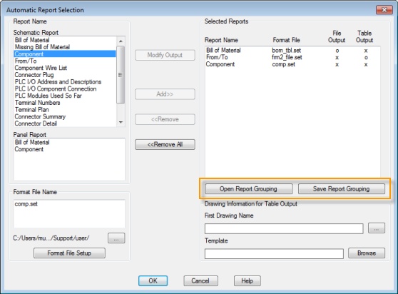
Table Output
If any of your selected format files contain table output, the program checks for any existing tables for the selected report. If an existing table meets all of the following conditions it is considered a match to the current report and updates.
- The existing table is for the same report, for example Schematic Bill of Material; Normal Tallied Format.
- The existing table is for the same scope, for example Active Drawing or Project.
- The existing table used the same format file. If the table was inserted without specifying a format file, it is a match if you do not use a format file for the report you are running.
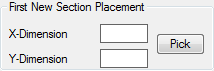
If no matching tables are found, the report tables insert on new drawings. If you are running multiple reports with multiple table output, each report inserts new tables on its own drawings. You can specify the first drawing name and the template name for any new drawings. Subsequent drawing names generate automatically by incrementing the previous drawing’s name.
Define the insertion point in the format file, otherwise the table is inserted at 0,0 coordinate value by Automatic Reports.
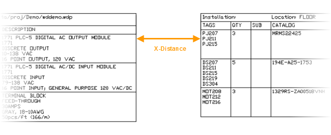
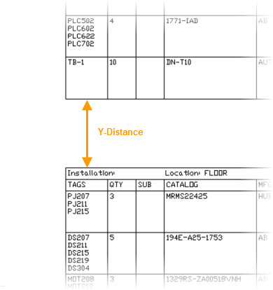
Breaks in a report table can be defined either by using the Special Breaks option or by defining a specific number of rows per table section. If your table contains breaks and multiple table sections per drawing, define the distance between table sections in your format file.
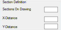
The X-distance and Y-distance values define the distance from the end of one table section to the beginning of the next. It is used when multiple table sections for one report are on the same drawing. A blank value is interpreted as zero.
Support for electrical standards
In addition to supporting the latest electrical standards, the Electrical toolset continues to provide the JIC and older IEC symbol libraries for legacy support.

AutoCAD Electrical toolset provides library symbols that comply with the standards:
- IEEE 315/315A
- IEC-60617
- NFPA
The IEEE and IEC library symbols are metric. To scale the symbols for imperial, use the Modify library symbols utility. The NFPA library symbols are in inches.
The JIC standard is no longer updated and was incorporated into the NFPA 79 standards. The NFPA standard states that the library symbols are in accordance with the IEEE 315/315A standard. AutoCAD Electrical toolset continues to provide the JIC and older IEC symbol libraries for legacy support.
Easily manage projects
Use the Project Manager’s time-saving features to boost productivity and simplify your project. Re-tag components, easily make changes to your file, and access simple export options

Circuit design and reuse
Simplify your electrical design with Circuit Builder. Access prepopulated data to build and annotate a sampling of motor control and power feed circuits.

The Circuit Builder tool comes prepopulated with data to build and annotate a sampling of motor control circuits and power feed circuits. Circuits include 3-phase, single-phase, and one-line circuit representations. Each circuit is built dynamically, adjusting the power bus to match the wire bus for the drawing, adding wiring between components, and annotating the elements with suggested values based upon the selected load. Each time a circuit is configured, it is added to a history list of circuits. This list provides for quick reinsertion at a later time.
Three items control this feature:
- The spreadsheet defines the available circuits, circuit types, and defaults for each option within a circuit.
- The template (.dwg file) for a selected circuit defines the wiring and the placement position for the individual components on that wiring.
- The electrical standards database provides suggested values used to annotate components of the circuit and the wire size and type of the power wiring.
Circuit Builder is customizable. You can add new circuit definitions and edit existing ones.
One-line motor control
Circuit Build supplies and uses a one-line symbol library when building a one-line circuit. Each one-line symbol has a WDTYPE attribute with a value of “1-” or “1-1”. The WDTYPE attribute value distinguishes the one-line symbol from a schematic symbol. A schematic symbol either has no WDTYPE attribute or a blank WDTYPE attribute value. One-line symbols follow the same symbol naming conventions and have the same attribute requirements as schematic symbols with a few attribute exceptions.
Workflow
- Circuit Builder opens the spreadsheet and reads in the first sheet named “ACE_CIRCS”.
- Circuit Builder shows the list of defined circuits in the Circuit Selection dialog box.
- Select a circuit to insert or configure. The associated line from the ACE_CIRCS sheet provides the base drawing template name, and the name of a circuit code sheet. The circuit code sheet is a separate sheet within the Circuit Builder spreadsheet.
- The base drawing template for the circuit inserts at your selected location.
- Circuit Builder finds and reads the attributes on all the special marker blocks on the inserted drawing template.
- Circuit Builder matches each marker block to a specific section in the circuit codes sheet. This section can be a single spreadsheet row or multiple consecutive rows in the circuit codes sheet. The section identifies one of the following:
- The action taken at this marker block location in the circuit. For example, calculate a wire type, insert a wire number, or adjust rung spacing.
- Provides a list of component insertion options that can be inserted at this point in the circuit. For example, presents a selection list containing a fuse, circuit breaker, or disconnect switch symbol.
Each marker block is processed in sequence, controlled by an ORDER attribute value carried on each marker block
- A marker block can insert a nested template into the main circuit template. If the nested template carries its own marker blocks, these marker blocks are added to the overall list to process. When all marker blocks have been processed, the circuit is complete.
SQL catalog support
Save time with SQL catalog database support. When you generate a Bill of Materials in Autodesk Vault, the data from your AutoCAD Electrical drawings will be automatically added to the report, including the details in the catalog database.

AutoCAD Electrical 2022 now supports the SQL catalog database for the Bill of Materials in Autodesk Vault.
When generating the Bill of Materials in Autodesk Vault for an AutoCAD Electrical project, the data from the AutoCAD Electrical drawings including the details in the catalog database are added to the report.
In addition to Microsoft Access database, the support is extended to the Microsoft SQL format of the catalog.
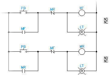
Coil and contact cross-referencing
Simplify your projects by keeping track of parent/child contacts in real time while Circuit Builder dynamically builds the circuit, assigning each component a component tag.

As Circuit Builder dynamically builds the circuit, each component receives a component tag. A child contact must link to a parent component to receive the same component tag as the parent.
The parent and child components are automatically linked by Circuit Builder if they each have the same default tag value. For example, the motor starter coil and auxiliary contacts both have a default value “M”.
There can be more than one parent/child relationship within the overall circuit with the same default tag. The overall circuit includes the main circuit template and any branching or nested circuit templates. For example, a reversing motor starter has two starter coils, forward and reverse. Each parent coil must link to the correct child auxiliary contacts and power contacts but they might all have the same default tag value, “M”. To accomplish the correct parent/child links follow these steps.
- Open the circuit template drawings that contain the parent and child marker blocks. There can be more than one circuit template drawing involved, for example a main template with power contacts and a nested template with the starter coils and interlocking auxiliary contacts.
- Find the correct marker block for each component that requires a new default tag link.
- Edit the MISC1 attribute value adding “_PRETAG={new default tag link}”. For example, add “_PRETAG=MF” for the forward motor coil and contacts, and “_PRETAG=MR” for the reverse motor coil and contacts.
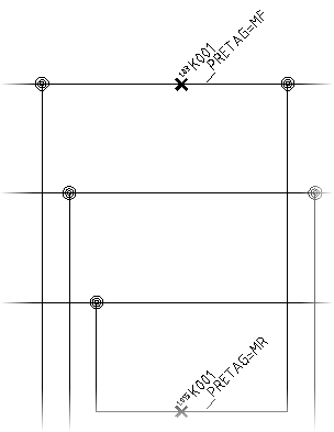 Note: The MISC1 attribute value can contain multiple special text flags which direct Circuit Builder to handle the component or underlying wire in a special way. When you add new values, do not overwrite any other special flag values. Separate each one with a semicolon.
 - Save the circuit template drawings.
When Circuit Builder inserts the nested circuit containing the child contacts, it matches these predefined tag values with the correct parent coil.
PLC I/O drawings from spreadsheets
Speed up your workflow by using a single data file to generate multiple drawings. Define a project’s I/O assignments and generate PLC drawings automatically from a spreadsheet, database, or comma-delimited text file.

Generates a set of PLC I/O drawings from a data file.
Find
Command entry: AESS2PLCChoose the data file and click Open.
List of Options
The following options are displayed.
Settings
Choose a .wdi file to apply previously saved PLC settings. If you enter the name of the .wdi file, these locations are searched in the following order:
- User folder: C:\Users\{username}\AppData\Roaming\Autodesk\AutoCAD Electrical {version}\{release}\{country code}\Support\User\
- Active project’s .wdp file folder
- Symbol library paths defined for the active project
- AutoCAD Electrical toolset lookup folder: C:\Users\{username}\Documents\Acade {version}\AeData\
- AutoCAD Electrical toolset support (C:\Program Files [(x86)]\Autodesk\AutoCAD {version}\Acade\Support\{language code}\.)
- All paths defined under AutoCAD Options
 Files Support Files Search Path
- Setup
-
Click Setup to display the Spreadsheet to PLC I/O Utility Setup dialog box where you can define:
- Number and type of ladders
- Number and spacing of rungs
- Reference number style
- Style, scale, and placement of modules
- Placement and spacing for inline devices
- Drawing template for new drawings
Note: If you choose a .wdi file after you make changes in the Spreadsheet to PLC I/O Utility Setup dialog box, the settings in the .wdi file override any changes made.
Ladder Reference Numbering
Controls options that relate to line reference numbers on ladders.
- Start: Specifies the first line reference number for the first ladder of the first drawing. Leading zeros and embedded alphabetic characters are supported for line reference numbering.
- Index: Specifies whether line reference numbers should increment by 1 or by another value.
- Column to column: Specifies how to calculate the first line reference number of the next ladder column on the same drawing.
- Next sequential number: Increment by 1 from the last number of the previous ladder column.
- Column to column count: Increment by a specified amount from the first line reference number of the previous ladder column.
- Drawing to drawing: Specifies how to calculate the first line reference number of the first ladder column on the next drawing
- Next sequential number: Increment by 1 from the last number of the last ladder column on the previous drawing
- Drawing to drawing count: Increment by a specified amount from the first line reference number of the first ladder column on the previous drawing.
Module Placement
- Always start at top of ladder
- Starts each I/O module at the top of a ladder, one module for each ladder.
- Same ladder only if module fits
- Builds the module in the ladder with the previous module if it fits completely. If the entire module does not fit, it builds in the next ladder or next drawing.
- Fill ladder – allow module splits
- Builds the module in the same ladder with the previous module and splits the module if necessary. If the module splits, it continues in either the next ladder or next drawing.
- Rungs between
- Skips the specified number of rungs between modules when multiple modules are placed within the same ladder.
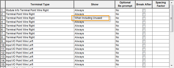
- Include unused/extra connections
- Includes the terminals defined as When Including Unused in the PLC database definition for the PLC module.
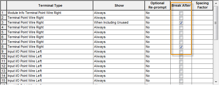
- Allow pre-defined breaks
- Automatically breaks the PLC module based on any breaks in the PLC database definition for the PLC module.
Drawing File Creation
Use active drawing
Indicates to use the active drawing to begin the PLC placement process. If a starting file name has already been entered, this option is not available.
Starting file name
Specifies the drawing file to begin the PLC placement process. The .dwg extension is not required. The drawing is saved in the same folder as the .wdp file for the active project.
Pause between drawings
Displays a dialog box before each new drawing is generated, which enables you to adjust the settings.
Free run
Generates all PLC drawings without stopping.
Sheet
Enter a value for the drawing sheet number. Sheet numbers increment for each new drawing.
Add new drawing to active project
Adds newly created drawings to the active project. The new drawings are added to the end of the project’s drawing list.
Need Autodesk AutoCAD support?
If you would like to purchase AutoCAD licenses or need support, please contact us at info@microsolresources.com. Our team will assist you in getting the assistance you need.
INDUSTRIES: MEP Engineering