In the 3D printing world, the main focus is printing geometry with color. That means that other things used in rendering such as lights, special effects, cameras, etc; are ignored.
The 3D Systems printer comes with proprietary software called 3DPrint. 3DPrint is where you import your various types of files including (.stl, .3ds, .wrl). The 3DPrint software can tell you if a model has reversed faces and show you a 2D view of each layer that will be printed. The program can also scale, rotate, position, and even mirror parts inside the build chamber. The size of the build chamber depends on the model of the 3D Systems printer that you are using.
3D Systems’ machines range from 8” long (X-axis) by 10” wide (Y-axis) by 8” deep (Z-axis) with the ProJet 460 and 15” long (X-axis) by 10” wide (Y-axis) by 8” deep (Z-axis) with the ProJet 660. The average build time for parts is around 1 hour per every inch built in the Z-axis.
General Information
1) Three-Dimensional geometry used for 3D printing can be generated in any 3D modeling application.
Common applications are Autodesk’s 3ds Max, AutoCAD, Revit, Fusion 360; and Rhino from McNeel.
2) All geometry to be 3D printed must be in three-dimensions. Any two-dimensional geometry cannot be processed by the machine’s software or interpreted by the 3D printer.
3) One way to check your geometry accuracy is viewing your STL file in an STL viewer. Some programs to look into are Netfabb and Meshmixer by Autodesk.
4) All three-dimensional geometry must consist of closed volumes.
An easy way to test for this is by checking the model’s volume. If the CAD software can calculate a volume it’s generally because the model consists of closed volumes.
In Netfabb you can run one of the repair scripts and that will attempt to automatically repair open contours and edges. Usually it is able to take care of any issues without much user input but sometimes a manual repair is required. Sometimes the changes may need to happen in the native application.
5) Ideally all geometries are unified to create a single object.
6) It is standard procedure to share screenshots, conduct webinars, and exchange emails to ensure proper interpretation of your file and setting customer expectations.
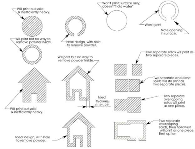
Minimum Thicknesses
1) Thicknesses needed for accurate and high-quality 3D printing may range based on the specific geometry.
2) The purpose of having minimum thicknesses in the file is to ensure that the printed output is accurate to the file’s geometry and meets expectations of quality.
3) Meeting minimum thicknesses can be a challenge if the model was not modeled for 3D printing. Especially in architecture, scaling to such a large degree causes many components to surpass the machine limitations.
4) The minimum thickness is also depending on the type of 3D Printer being used. There are high-resolution 3D printers and low-resolution 3D printers.
5) Exceeding the machine’s resolution capabilities may result in lost geometry.
6) As a general guide we use 0.04” as the minimum thickness for walls, beams, pillars, etc. But it is height dependent.
Example: 1/2” tall pillar at model scale would require a minimum thickness of 0.04”. Increasing the thickness, however, to 0.06” or 0.08” would produce a smoother and more accurate pillar. (Since the look of the model is critical to communicating design intent we understand that both thinness and smoothness are very important. In some cases we recommend extruding the geometry to the inside of the model, somewhat hiding the ‘thickening’. The resulting pillar maybe 0.04” (x) and 0.06 (y) and create a smooth and visually accurate model.)
If however, the pillar is 2 inches in height, a thickness of 0.1” may be needed to be accurately produced since it’s much larger it would need more ‘structure’ to keep it strong. In summary when we’re talking about fine, thin geometry, the larger or taller the geometry, the thicker it will likely need to be.
Exporting Guidelines
1) Once you have checked that your file consists of only three-dimensional closed volumes you are ready to export your file.
2) Translate your model to the HOME axis of 0,0,0
3) Scale your file to the final print output size
4) Change the units in your application to either inches or millimeters. When files are transferred between 3D applications the only information that transfers is the unit numbers, not the unit measurement, such as feet, inches, meter, etc. Thus, after you scale, if you change your units to inches then it becomes a breeze to transfer files between 3D applications.
5) Exporting an STL file usually involves the ‘Export’ or ‘Save As’ function. STL is the most common file format for use in 3D printing. Your three-dimensional design will be converted to a three-dimensional triangulated polygon mesh, made up entirely of triangles. STL stands for Stereolithography
6) BIM data, file history, XML data, or any other information associated with the model that was contained in the native application will not be available in STL format. An STL file contains only an X, Y, and Z coordinate for each point that makes up the individual triangles. The points are based on the universal world coordinate system.
7) If your application does not export to STL the next preferred file formats are .3ds and .dwg. This format can be brought into almost any 3D CAD application and exported to STL from there.
8) After you’ve exported your file it is good practice to review the converted STL file in an STL viewer. You can view the STL in many 3D modeling applications but an STL viewer is sometimes easier to see where errors may be located.
Below is a picture of ideal printing for the 2D layers of a print. These are the layers that you can see in the 2D view and they show what is going to be printed on a specific layer.
Created by: 3D Systems, NRI 3DLab, Andrew Esquivel Peak Solutions, DMC London; The Bartlett School of Architecture / CADCAM and the Bartlett workshop, University of Penn School of Design, McNeel (Rhino), CADSpan, ZCorporation, and Microsol Resources.
If you have any questions or need advice on 3D printing, feel free to reach out to our team at 3dprinting@microsolresources.com.
The release of Rhino 7 is the most significant in the 30 years since Rhinoceros3D was first introduced. At its heart, RhinoCommon offers a powerful geometry engine with high mathematical accuracy, and with new features like SubD modeling and Clash Detection, it is only getting better.
If you haven’t already purchased a license of Rhino 7, I hope that by the end of this article you are convinced that it provides huge value out-of-the-box and great potential in the future.
Rhino3d.com/7/new/ lists all of the new features and capabilities of Rhino 7. For ease of navigating, links to some of the best features are listed below:
Grasshopper was packaged as part of Rhino 6, and now with the GH Player, Plugins can be built to receive User Defined Inputs without the need to open and run the Grasshopper definition.
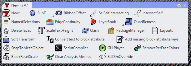
A full list of all of the new Commands that are available. For quick reference and similar to past versions, there is a tab called New in V7 which has some of the best new commands.
In addition to all of these new and enhanced features that come with Rhino 7, there is much effort afoot to bring the capabilities of Rhino into almost any environment (Rhino.Inside).
The foundations of Rhino are ready for broader and deeper applications of its capabilities. As plugins for Rhino have been developed over the years, it has spurred a thriving developer community with advanced tools for data and geometry manipulation.
In Version 6, Rhino was made into a Dynamic Link Library (DLL), which allowed for a couple of things to happen in the development of Rhino 7:
A. Plugins (particularly C++) developed for Rhino 6 will work with Rhino 7 and possibly later versions without breaking the SDK.
For scripters, this provides a more solid footing for the development and support that would be necessary for plugins.
For Firms and BIM/VDC Managers, this gives more long-term reliability in the tools that are incorporated into certain workflows
B. Rhino can be run as a plugin within other applications
Standalone Console Apps / .NET Web Servers (Rhino Compute)
CPython
Revit (Rhino.Inside.Revit)
Rhino Compute lets Rhino run on a .NET Web Server, effectively bringing Rhino to the cloud. Startups such as Hypar are working to bring Grasshopper scripting and much more to the web browser, allowing for design input to come from anyone, anywhere.
The most popular flavor of the Rhino.Inside technology is Rhino.Inside.Revit (beta, free), which has effectively made Rhino 7 the largest possible plugin for Revit. Not only is it the full version of Rhino running within Revit’s memory space, but all of the plugins are compatible with Rhino 7 as well. Plugins that had been developed for Rhino 6 remain compatible, so the functionality that is part of many scripts and workflows can endure.
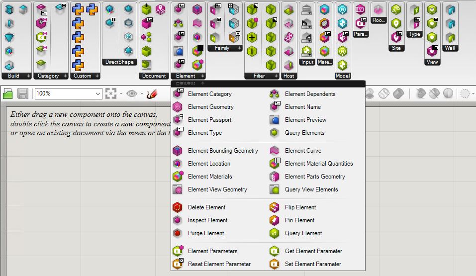
There are new Grasshopper Components found in V7, with the majority available within Rhino.Inside.Revit, in the Revit Tab.
Rhino 7 provides a framework with minimal barriers to entry. From the lone wolf coder to the multi-national firm, Rhino 7 can be very powerful if leveraged properly. A great conversation with Steve Baer, Luis Fraguada, and Will Pearson of Robert McNeel & Associates can be found on ProArchitect’s Youtube page. They discuss the rationale and forward-thinking concepts behind Rhino 7 and the Rhino.Inside technology, but for the most part, opine on Rhino Compute.
New York, NY, October 9, 2017 – Microsol Resources, a 3D Systems Authorized Reseller and an Autodesk Platinum Partner with offices in New York, Boston and Philadelphia, is pleased to announce that David Spergel has joined the company’s New York office as a 3D Printing Specialist.
David will be responsible for providing installation, training, service and support for our client’s 3D Systems Professional 3D printers, including 3D Systems’ CJP, MJP, and ProJet lines. Prior to joining Microsol Resources, David worked as a Production Manager at Doob3D where he trained and managed the production team. David holds a Bachelor of Science in Manufacturing Engineering from Boston University.
“We are excited to have David join our team and serve as a new resource for our 3D printing clients whose needs include 3D printer support and maintenance of 3D printer service contracts,” said Emilio Krausz, President of Microsol Resources. “His technical support experience and 3D printing expertise will be especially valuable for our existing clients in the industry.”
Features the latest informative and technical content provided by our industry experts for designers, engineers, and construction firms and facility owners.