As of April 30, 2025, we’re proud to announce our exciting new chapter. | Read more here.
Rhino.Inside.Revit version 1.0 was released mid-August of 2021, containing all of the features that Robert McNeel and Associates wanted to include in the initial release, including the much awaited Element Tracking. Since this release, more users and firms have begun adopting Rhino.Inside.Revit into their workflows.
Additionally, there have been minor updates and improvements provided in the release of Rhino.Inside.Revit v1.1 and the latest release of v1.2, currently available as an update from within the Revit toolbar. This article will cover some resources for learning, as well as cover the best features of Rhino.Inside.Revit, updated to the latest release (v.1.2) that is available.
Rhino.Inside.Revit has been around for a couple of years, but here’s a recap, at a high-level, of the capabilities of Rhino.Inside.Revit:
Read access to the properties and parameters for a given Revit model element
Edit access to the parameters for a given model element
There are a variety of Create components that allow for the creation of new Revit elements with provided inputs. The following Revit elements can be created with the Create components in Rhino.Inside.Revit:
Beam, Column, Roof, Wall, Floor, Level, Grid line, Adaptive components, Family instance, DirectShape, Topography, Building pad, 3d view, Form / loftform, Model line, Sketch plane, Model group, Material, Physical asset, Thermal asset
Note: due to the new feature of Element Tracking, many more Create components should now be possible, so keep an eye out for updates in the Release Notes.
By specifying a particular view, the visible geometry for an element can be converted into Rhino geometry. The resulting geometry could be Points, Lines, Curves, Meshes, Surfaces or Polysurfaces.
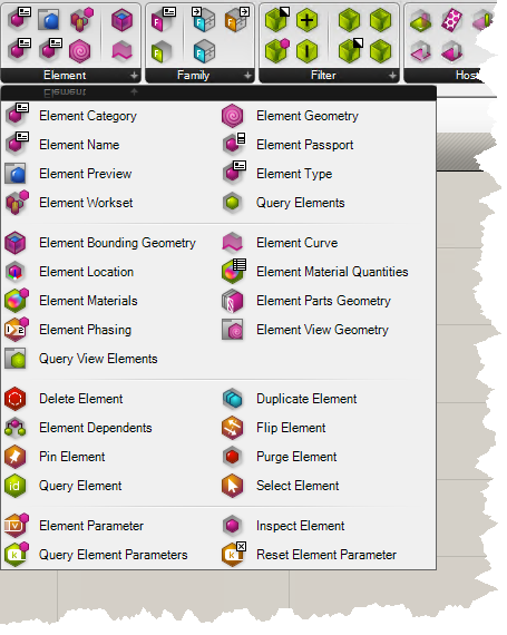
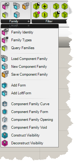
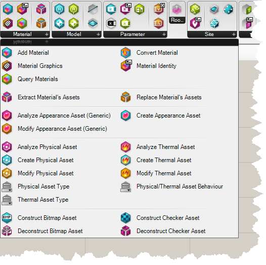
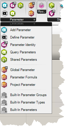
Within the nearly 300 different components that are available, Rhino.Inside.Revit has a great deal of functionality. The components are grouped into various panels across the ribbon in the Revit tab:
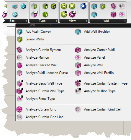
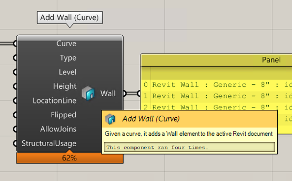
This is a short summary of the many components that are available. I recommend giving the full list of Components a review, and as always, make use of the tooltips in Grasshopper by hovering over the middle of the component.
One of the nicest new features Rhino.Inside.Revit is the introduction of Element Tracking to all of the Create Components, which allows the Grasshopper script to remember the elements it created between sessions.
Previously, in Beta versions, Grasshopper script would have no memory of having created elements between sessions, so if the script was opened in a new Revit session, it may create duplicate elements.
In the public release, there is flexibility for users to define how they want the Grasshopper components to remember the Revit elements that they created:
![]()
Disabled will not track the elements, so will create new (and possible duplicate) elements upon solving.
Enabled : Replace deletes any existing element and creates a new element, generating a new Element ID.
Enabled: Update will check to see if it can edit the existing element (maintaining the Element ID). If it is unable to edit or does not detect any existing element, it will create a new element. This is the default setting.
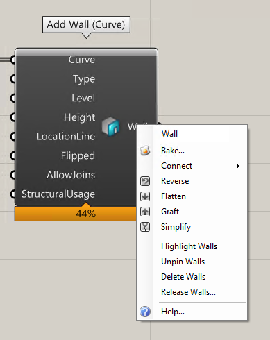
In addition to the Tracking Modes, users can Highlight (elements will be selected within the Revit window), Unpin, Delete, or Release the elements by right-clicking the Output of the component.
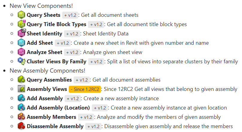
Version 1.2 brought a dozen new components for Views, Sheets, and Assemblies.
When considering implementing a new software or update into a firm’s standard practices, it is good to test and understand any changes made in each release. Here is a shortlist of some of the most useful links for learning about the latest releases of Rhino.Inside.Revit.
Great launching pad for accessing resources and getting started with Rhino.Inside.Revit.
Download links, installation instructions, and basic how-to videos and GIFs to get started.
Deep dive to understand the underlying concepts behind the Revit model data and the Rhino.Inside.Revit components available in Grasshopper.
Watch videos and content covering Rhino.Inside.Revit from the community.
Ask questions, ask for help, discuss topics, or get help or advice with issues experienced while using Rhino.Inside.Revit.
This page contains reference guides for users, developers and BIM Managers, including the Release Notes, which are a quick way to get up to speed with the latest changes so that any existing Grasshopper definitions will continue to work as expected, or can be planned to be revised accordingly.
This blog contains great information about the Forge and Revit APIs, which can be helpful to understand how Rhino.Inside.Revit is able to work, and how the functionality can be extended through scripting.
As a reminder Rhino.Inside.Revit is free to download and use, and the source code can be found on Github. You just need a license of Revit and Rhino 7 and you should be up and running! Email rhino@microsolresources.com to purchase new or upgrade to Rhino 7.
Rhino is an amazing tool for modeling and rationalizing complex geometries. Revit is a great tool for storing and managing a BIM project. With the recent release of Rhino 7 (or Rhino 7 WIP), and the creation of the Revit add-on Rhino.Inside Revit, it is easier than ever before to create BIM assemblies from complex geometries that can be scheduled and sectioned properly.
In this post, I will provide a step by step workflow for creating a space frame with complex geometry, using the tools available in Rhino 7, Grasshopper (GH), Rhino.Inside.Revit (RiR), and Revit.
The tools that will be used are the following
If you haven’t used Rhino.Inside.Revit before, it may be best to review the installation requirements and instructions. Once everything is installed and ready to go, the Guides and Samples should provide enough of a footing to begin working with Rhino.Inside.Revit. If this is also the first time using Grasshopper, then I recommend reviewing these Grasshopper Tutorials and checking out the many instructional videos on YouTube. The Masterclass on Data Trees by David Rutten is particularly helpful for understanding the data structure that Grasshopper uses.
Before starting the process of creating a space frame, I am going to layout the general series of steps that will be taken to achieve this:
This is a general outline for creating a space frame, and there is a lot of flexibility for design and customization. Finding an appropriate balance of automation and designer input will ultimately be determined by the designer, and the features of Rhino.Inside.Revit help to empower the designer by providing more means to produce.
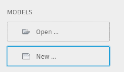
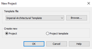
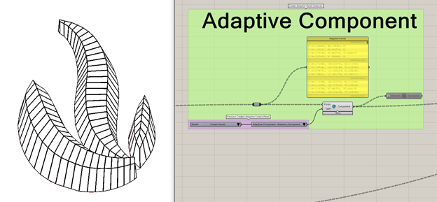
The first steps will be to create a new Revit model and 4-point Adaptive Component:
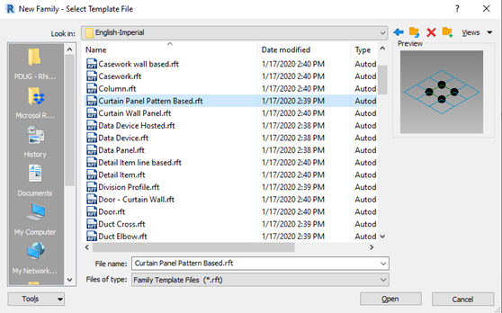
For this example, I chose the Family Template ‘Curtain Panel Pattern based.rft’ which already has 4 adaptive points ready to go.
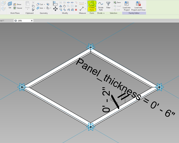
The first step in the Adaptive Component is to create a profile that will be extruded around the perimeter of the panel, creating the frame. If a frame were created from the profile shown below, it would create a 2”x6” frame.
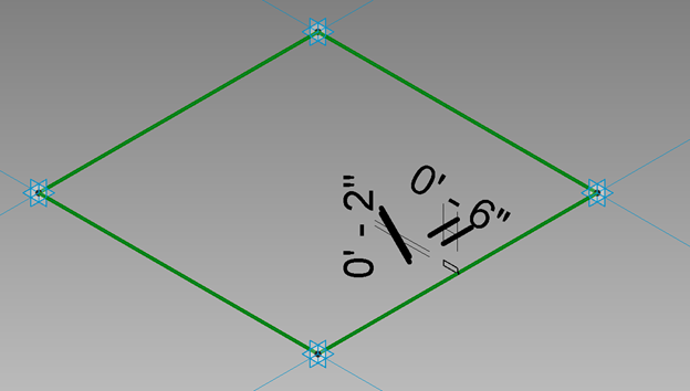
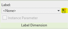
However, in this example we want to have the ability to modify the thickness of the frame for each instance depending on position and orientation. For this exercise, select the 6” dimension and in the Contextual Modify Tab click the icon to Create Parameter:
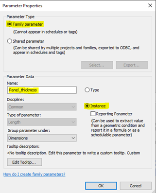
Specify a Name and then make sure that it is a Family Instance Parameter. This will associate the parameter with this Family and allow for each instance to have a different value for the parameter. By default, the parameter will have the same value as the dimension before creating the parameter, but can be changed later in the settings. For this exercise, all instance parameters will be modified so the default value does not have as much consequence.
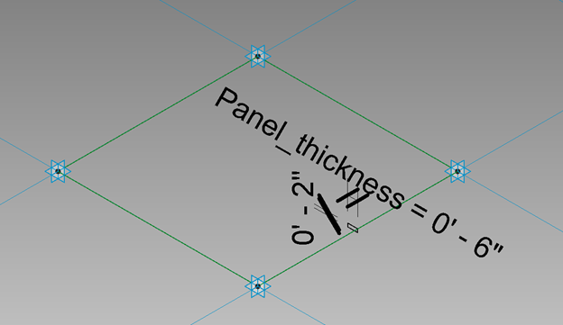
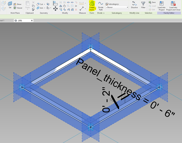
Now that the parameter has been created, the form for the frame can be generated by selecting the rectangular profile, and the reference lines that connect each Adaptive Point, the selecting Create Form.
Revit will intelligently extrude the profile along the reference lines.
Now, if the Panel_opening parameter is modified, the Family Instance will be changed accordingly. From here a 2D surface can be created by selecting the reference lines and pressing Create Form.
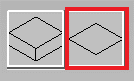
There will be two options available. When creating a proper Adaptive Component, the panel should be modeled as it will be build. For this exercise, however, we will choose simple modeling techniques. After selected Create Form above, two options will be presented:
Choose the 2D surface:
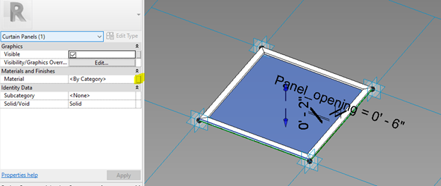
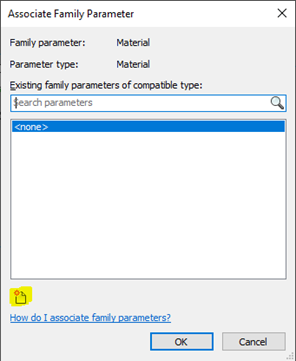
Once created, select the 2D surface and in the Properties panel, click the button all the way to the right for Material to Associate with Family Parameter.
In the dialog that pops-up, click the icon in the lower left corner to create a new parameter:
In the Parameter Properties dialog, choose Family, name the Parameter, and choose Instance again. Revit recognizes that this is a Material Parameter and specifies that accordingly.
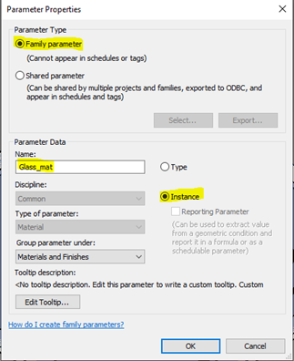
After creating the Material Parameter, apply it to the 2D surface. This parameter will be driven later by the Grasshopper Script with Rhino.Inside.Revit components. Now that a simple Adaptive Component has been created, Insert into the Host RVT. Each instance of this Adaptive Component can now be driven by:
In the Ribbon, navigate to Add-ins (or the tab that says Rhino.Inside) and click the Rhino icon that is labeled Start
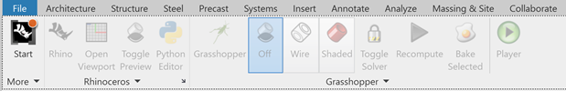
Once the plugin is loaded, many of the buttons that were previously grayed-out will show as active and can be opened.
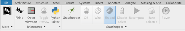
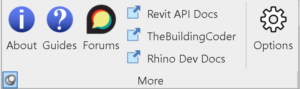
From Left to Right the buttons are:
Start– Within the panel under ‘More’ are buttons to information about the version of Rhino.Inside.Revit, Guides, Forums, Documentation and Blogs on the Revit API, as well as various options
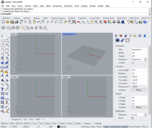
Rhino– Opens Rhino 7 window
Open Viewport – Opens a minimalist window with a view into the Rhino Viewport
Toggle Preview – Toggle Rhino Model preview visibility
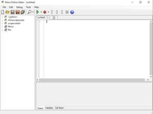
Python Editor – Opens a Python window for Rhino
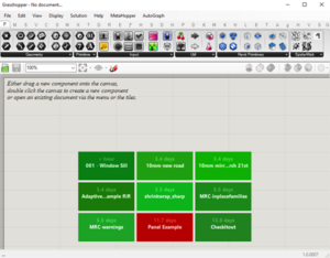
Grasshopper – opens the GH window
Preview Geometry – OFF, Wireframe, or Shaded Rhino Preview Geometry
Solver – Turn solved ON or OFF for Grasshopper canvas (this controls whether the GH script is run automatically or not)
Recompute – Rerun the Active Grasshopper Script
Player – Run GH scripts without opening the GH window
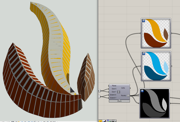
This example will create a space-frame, but to begin, I am going to load an image (The Microsol Resources Logo) into the image sampler in Grasshopper:
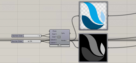
This can be added to Grasshopper by dragging and dropping it into the Grasshopper canvas. This automatically loads an image into the Image Sampler component, as shown above. For this exercise, the image is a PNG has a transparent background. The image is 256×256 pixels, so by feeding in a 256×256 array of points into the Image Sampler, I can extract pixel information from the image.
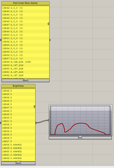
The top (color) image is extracting the Red, Green, and Blue values of the pixels, and the lower (grayscale) image is extracting the brightness. These RGB values can be used to drive material parameters, such as the Tint color for the newly created Adaptive Component Material Parameter “Glass-mat”.
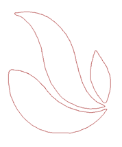
We’ll come back to this, but first, we need to start creating the geometry that will drive the Adaptive Components. Either with a simple script, or by tracing over the boundary of the three (3) distinct objects in the image, closed planar curves can be generated:
These curves can then be subdivided in a multitude of ways in Grasshopper. For this exercise, I am automatically subdividing each curve into Quads (a curve with 4 vertices) with the Quad Remesh Component:
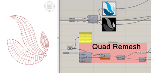
This ensures that I can deconstruct each subdivision into four (4) vertices, which can later drive the Adaptive Components. If desired, I could use the vertices to drive the Adaptive Components right now on the subdivided planar surface, but before I do I want experiment with more Grasshopper components.
Kanagaroo provides tools for running physical simulations on Rhino objects. In this example, I want to keep all of the points that lie on the perimeter of the boundary curves anchored to the floor and apply a directional force to all of the remaining vertices and line segments. To do this, all vertices on the perimeter are determined and fed into the Anchor Kangaroo Component (Perimeter Anchor Points, below) which constraints those points in all XYZ directions:
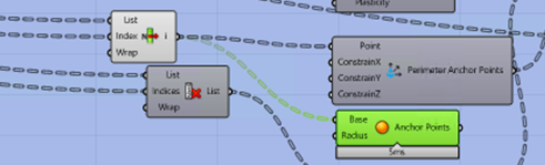
The anchored points are identified as small green spheres in the image below:
In addition to anchoring the perimeter points, each of the line segments must have a way to respond and adapt to the forces being applied. To accomplish this a Spring Force is created from each line segment:
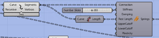
These Springs will generate a response to other forces being applied. Parameters such as Stiffness and Damping, may need to be adjusted so that the simulation converges to an equilibrium. If the forces are too extreme, then the resulting geometry could be crushed or stretched into a form that is undesirable.
Along with the Spring forces, a Unary Force is applied as a lifting force to every other vertex not on the perimeter. This is like creating a catenary curve from a gravitational force, but inverted, so the force is applied in the positive-Z direction.

It is important to keep in mind that all of the forces are dimensionless, but their magnitudes relative to each other will determine how the simulation plays out.
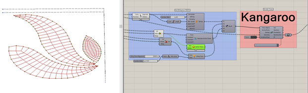
When all the forces have been created and fed into the Kangaroo Solver Component, the simulation can be run. At any time, or once the simulation has come to an equilibrium, the Trigger can be stopped and the resultant geometry can be reviewed:
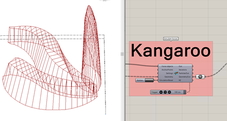
Tweaking the Number Sliders for the forces will change the resulting Geometry. When it reaches a good state, the simulation can be stopped and we have a wireframe spaceframe, with all quads intact flowing out of the GeometryOut node on the Kangaroo Solver Component. The vertices of each quad can now be extracted and used to create new Adaptive Component instances. From GeometryOut, the quads are exploded into points, grouped into fours.
Finally, the data is ready to pass to the Rhino.Inside.Revit (RiR) Components, which will serve as the anchor leg of this workflow. With the datatree of points fed into the RiR component Add Component (Adaptive), along with the Curtain Panel Family Type, default instances of each Adaptive Component will be created.
As you can see, each panel that was created has the same thickness throughout (6”). After creation, the parameters controlling thickness can be modified manually, or generatively.
Let’s assume we want the thickness to depend on the orientation of the panel. If more vertical, then the frame thickness will be smaller, and the glass panel will be larger; more closed if horizontal. The definition below takes in the points and determines a thickness, with maximum thickness determined by half of the smallest line segment in the panel. The output will drive the new value of the parameter Panel_thickness.
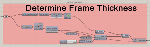
The RiR component Set Element Parameter requires three (3) inputs:
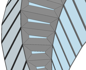
Connecting the calculated Panel_thickness parameters above, and the previously created instances of the Adaptive Component, the parameters can be modified with Set Element Parameter. Horizontal panels across the top of the middle structure are oriented more horizontally, and thus show nearly closed.
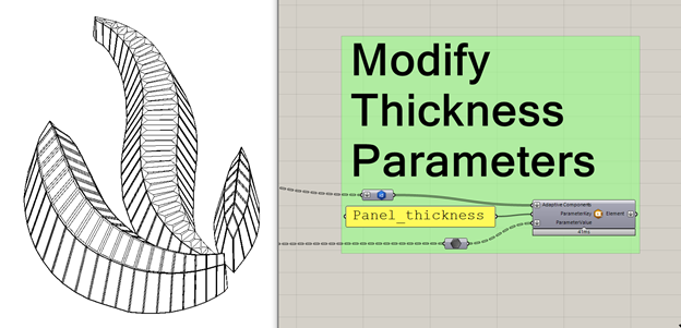
With the panel thickness adjustable down to each instance, it gives granular control over the output, which was specified in the Parameter when it was created within the Adaptive Component.
Now, if we rewind back to when we extracted the RGB values from the image, we can prepare the data to modify the Material Parameter Glass_panel.
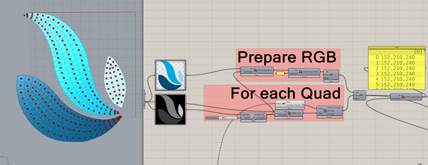
By comparing the pixel color in the image to the location of the panel, RGB colors can be assigned to panels. These RGB values are then used to create names for Material Assets that will have distinct colors. In this case, there are a total of seven (7) distinct colors, so seven different Assets and Colors will be created. These are all Grasshopper Components.
Note: Technically there are seven distinct colors detected by the Image Sampler, but this could reasonably be reduced to three (3) without changing the appearance much. Sometime high precision is necessary, but similar to Significant Figures from Mathematics it may be prudent to rationalize or round values so that custom fabrication costs are reduced.
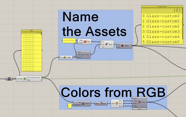
These names and colors are connected to RiR components Create Appearance Asset and Create Material. This creates seven new Materials and Appearance Assets, duplicated from the specified template material: Glass. The color is connected to the Color and Tint Color inputs for Create Appearance Asset.
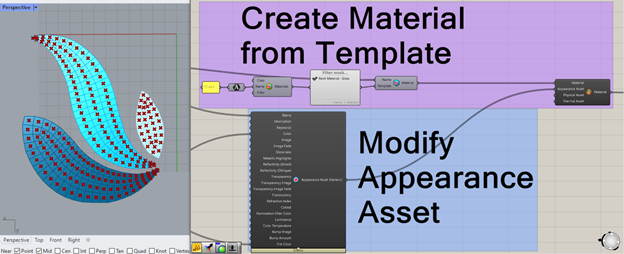
In the component Modify Material Assets, the newly created Assets and Materials are fed in so that the default Assets for Glass are swapped out for the new Assets. There is a lot going on in the background to make this happen.
Finally, with Set Element Parameter and connecting the 1) Adaptive Components 2) Parameter Key (Glass_mat) and 3) New Material Assignments, the Materials will be applied to each instance parameter, all originally driven by the pixel color in the image.
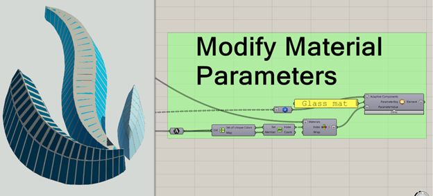
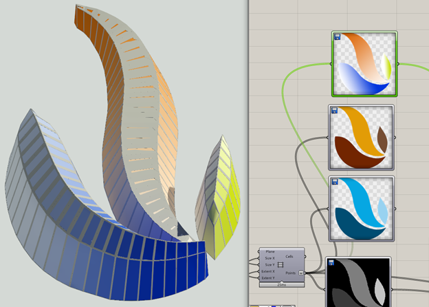
These colors can be changed later with ease simply by swapping the original image that was driving Material RGB values.
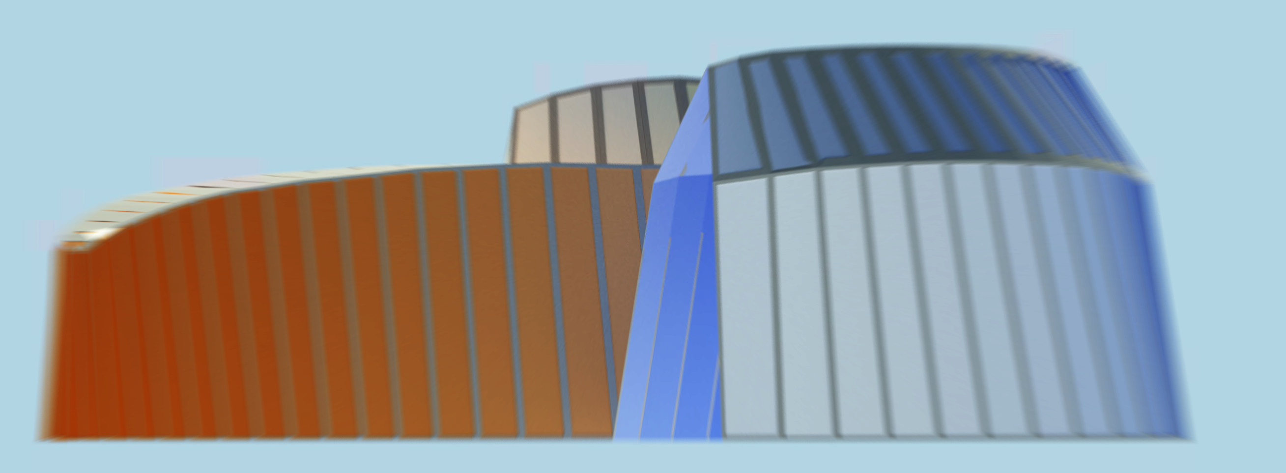
Or apply a gradient of colors across all of the panels!
This workflow is meant to demonstrate how BIM objects can be generatively designed in Revit, with the wealth of tools available in Rhino and Grasshopper. Rhino’s Geometry engine enables the creation of complex geometries, such as Non-Uniform Rational B-splines (NURBS) that would be impossible or very time-consuming to replicate Revit, but easy with Rhino.Inside.Revit. Beyond the base functionality of Rhino+GH, Food4Rhino is a great resource for free and paid plugins for Rhino and Grasshopper, and what has been presented in this post is just the edge of what is possible. Image processing can allow for a hand-drawn sketch to drive the creation of BIM objects, and audio processing can allow sound and music to drive parameters. This tool has the potential to revolutionize how designers generate and engage with Building Information Models; find your inspiration and let it flow!
If you are interested in a 4-hour workshop on Rhino.Inside.Revit, please review our class outline. Contact training@microsolresources.com with any questions and to schedule a class.

The release of Rhino 7 is the most significant in the 30 years since Rhinoceros3D was first introduced. At its heart, RhinoCommon offers a powerful geometry engine with high mathematical accuracy, and with new features like SubD modeling and Clash Detection, it is only getting better.
If you haven’t already purchased a license of Rhino 7, I hope that by the end of this article you are convinced that it provides huge value out-of-the-box and great potential in the future.
Rhino3d.com/7/new/ lists all of the new features and capabilities of Rhino 7. For ease of navigating, links to some of the best features are listed below:
Explore organic shapes quickly and easily
Rhino 7 can now be used as a plugin for Autodesk Revit, expanding the possibilities for both programs. More info below…
Quickly create a Quad Mesh from existing geometries, including SubDs
Detect and resolve clashes quickly.
Installing and managing plugins for Rhino+GH is now easier than ever, right from Rhino itself!
Grasshopper was packaged as part of Rhino 6, and now with the GH Player, Plugins can be built to receive User Defined Inputs without the need to open and run the Grasshopper definition.
From Enhanced Text Fields that work with Formulas to Layout Management tools, it is easier than ever to document your designs
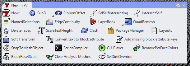
A full list of all of the new Commands that are available. For quick reference and similar to past versions, there is a tab called New in V7 which has some of the best new commands.
In addition to all of these new and enhanced features that come with Rhino 7, there is much effort afoot to bring the capabilities of Rhino into almost any environment (Rhino.Inside).
The foundations of Rhino are ready for broader and deeper applications of its capabilities. As plugins for Rhino have been developed over the years, it has spurred a thriving developer community with advanced tools for data and geometry manipulation.
In Version 6, Rhino was made into a Dynamic Link Library (DLL), which allowed for a couple of things to happen in the development of Rhino 7:
Rhino Compute lets Rhino run on a .NET Web Server, effectively bringing Rhino to the cloud. Startups such as Hypar are working to bring Grasshopper scripting and much more to the web browser, allowing for design input to come from anyone, anywhere.
The most popular flavor of the Rhino.Inside technology is Rhino.Inside.Revit (beta, free), which has effectively made Rhino 7 the largest possible plugin for Revit. Not only is it the full version of Rhino running within Revit’s memory space, but all of the plugins are compatible with Rhino 7 as well. Plugins that had been developed for Rhino 6 remain compatible, so the functionality that is part of many scripts and workflows can endure.
There are new Grasshopper Components found in V7, with the majority available within Rhino.Inside.Revit, in the Revit Tab.
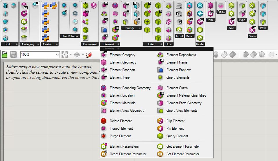
For more information on Rhino.Inside.Revit Technology, please refer to our other blog posts and our Microsol Resources’ Youtube Channel for additional resources and webinar recordings.
Rhino 7 provides a framework with minimal barriers to entry. From the lone wolf coder to the multi-national firm, Rhino 7 can be very powerful if leveraged properly. A great conversation with Steve Baer, Luis Fraguada, and Will Pearson of Robert McNeel & Associates can be found on ProArchitect’s Youtube page. They discuss the rationale and forward-thinking concepts behind Rhino 7 and the Rhino.Inside technology, but for the most part, opine on Rhino Compute.
Want to upgrade to Rhino 7 or have any questions about any of the New Features? Feel free to contact us at rhino@microsolresources.com.

Features the latest informative and technical content provided by our industry experts for designers, engineers, and construction firms and facility owners.
LEARN MORESTAY IN TOUCH
