


What’s New with Revit 2026?
By Microsol Resources, Graitec Group | BIM
Autodesk Revit 2026 brings a host of exciting new features and enhancements designed to improve performance, streamline workflows, and empower design teams across architecture, engineering, and construction. With a focus on better collaboration, increased modeling accuracy, and smarter documentation tools, Revit 2026 reflects Autodesk’s continued commitment to delivering user-requested updates. From faster view generation to more flexible design options and expanded interoperability, this release offers something valuable for both seasoned professionals and new users alike.
Here are some of the standout new features in Revit 2026:
Accelerated Graphics
Experience a significant navigation performance improvement in 3D and 2D views, helping you review your designs faster.
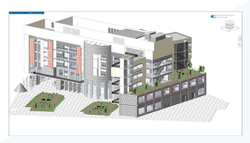
Use this tech preview to get early access to Revit’s new graphics platform, delivering faster navigation and optimized hardware utilization, with a current focus on the graphics card. Accelerated Graphics is enabled on a per-view basis, without creating any changes to the model or the view. When the view or model is closed, the accelerated graphics mode is disabled for that view.
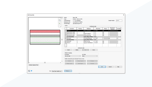
Allow Compound Structure without Core Layers
The core layer requirement in compound structures is no longer mandatory, making it easier to delete core layers or move layers outside the core boundary.
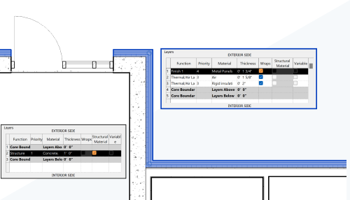
You can delete core layers or move layers outside of core layers to improve the default joins and support visibility control of finish walls and floors.
Best practice: To ensure the wall joins properly, move all the layers to the ‘Interior’ side if the wall is used as an interior finish, and make the ‘Interior Finish Face’ face the actual interior side. Apply the same rule for the walls used as exterior finishes.
Toposolid Enhancements
Toposolid tools have been enhanced including updates to sub-divisions and accuracy improvements.
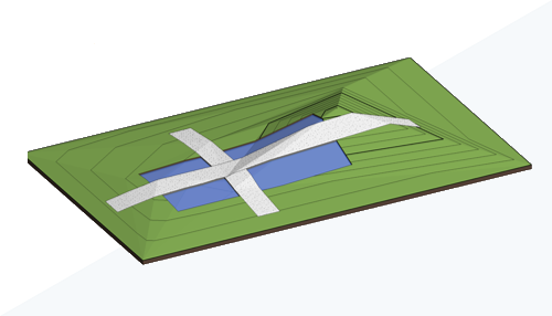
Sub-Division Enhancement
When creating a subdivision on a toposolid, a new sub-division is generated that follows the geometry of the host toposolid. You can provide an offset to the subdivision. A positive offset places the subdivision above the host, while a negative offset places it below the host. A negative offset excavates the host, and the excavation volume is reported in the properties of the subdivision. To create a subdivision that uses a different material than the host toposolid, change the toposolid type.
Subdivisions are a subcategory of toposolids. Use object styles and visibility/graphic overrides to control how subdivisions are displayed in views of your model.
Important: When upgrading models that use toposolids and sub-divisions, some legacy parameters are no longer valid.
- Inherit Contours – This is now controlled directly by the toposolid type used by the sub-division.
- Material – This is now controlled directly by the toposolid type used by the sub-division.
Layers used in compound structures such as a toposolid have a geometric limitation that must be greater than 0.8mm. If the original sub-division has a height less than 0.8mm, a type will be created with the minimum thickness. Graphically it will retain the height, position, and material of the original sub-division, and the bottom of the new sub-division will extend beneath the surface of the host toposolid.
Points Threshold
Two settings in the Revit.ini file control the number of points used on toposolids in your models.
- LinkToposolidMaxPointThreshold – Used when linking topograpghy to your model.
- NativeToposolidMaxPointThreshold – Used when creating toposolid elements from imported DWGs or text files.
Set the values for these in the Revit.ini file. The valid range is from 10,000 – 50,000. The larger number of points used to create toposolid elements will result in more accurate representation but may impact the performance when editing toposolids and/or when navigating the model. The default for both settings is 20,000 points.
If you change the value of a setting in the Revit.ini file, the setting will be applied to toposolids created after the change was made. Toposolids created prior to the change will not be affected.
Graded Region Volume Accuracy
The methods used to calculate the cut and fill volumes of a graded region have been revised for greater accuracy. Additional volumes beyond the boundary of the new toposolid are no longer included in the calculations. The volume is now calculated exclusively within the boundary of the new toposolid and projected upward.
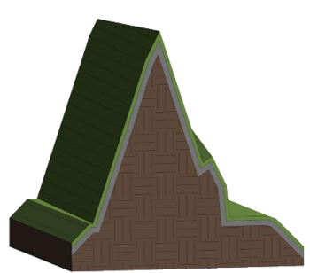
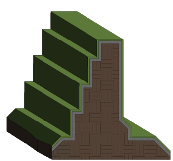
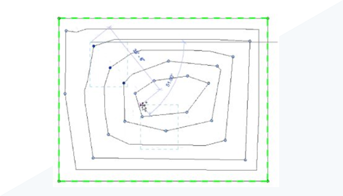
Improved accuracy when linking topography
When reloading topography linked in previous releases of Revit, the improved precision of linking may result in topography that more closely aligns with the geometry of the link. In some cases, you can successfully link topography that was not previously possible. See images below for example.
Source file to be linked
|
Before accuracy improvement |
After accuracy improvement |
|---|---|
 |
 |
Void Cut Stability
Enable Cut Void Stability in your models to increase the likelihood of successful cuts on some toposolids. The Cut Void Stability setting applies a small shift to the cut geometry at random along the x or y axis until a cut succeeds. The shift may slightly impact the accuracy of the void geometry. When Cut Void Stability is applied, any changes will be reported in a warning and in the journal file.
Sheet Collections: Custom Parameters and Schedules
Sheet Collection is now available as a category for both Parameters and Schedules.
You can see the new parameters added to the Sheet Collection category on every Sheet Collection node. The parameter values are synchronized to every Sheet included in that collection.
Parameter values show as read-only on every Sheet in the collection since they are driven by the Sheet Collection. If you modify the parameter value on the Sheet Collection, this updates the value for all Sheets (and Title Block Labels if included there).
If you move the Sheets into another Sheet Collection, the parameter value is automatically updated based on what is defined in that Sheet Collection.
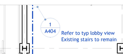
View Reference Enhancements
The view references have been enhanced including instance based reference labels and the ability to include shared parameter labels.
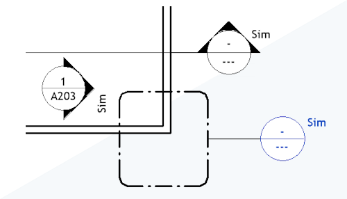
Instance Based View Reference Labels
Previously when placing a view reference that referenced another view, the view label was type based. This label is now instance based making view reference more flexible and easier to coordinate with your documentation standards. Make changes to the label on a view after it is placed by changing the value for Reference Label on the Properties palette. The default value assigned to the view reference is set by the type parameter of the view, Default Reference Label.
Shared Parameters in View Reference Family Labels
Add a label to a view reference family to display a shared parameter value defined as a project parameter to views in a model file. Editing labels and adding shared parameters is now possible for the following categories:
- Callout Heads
- Elevation Marks
- Section Marks
- View References
The workflow for adding shared parameters is identical to the workflow used for other supported family categories. In the model file, the shared parameter is assigned to the Views category.
Globalize Electrical Conductors
Manage circuit wiring requirements with controllable and customizable conductors and cable configurations.
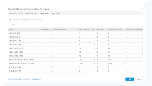
Electrical conductors and cables are customizable. The new Electrical Conductor and Cable settings allow you to define conductors and then use those conductor definitions in cable sizes and cable types. These cable types are then assigned to circuits in your models.
To access electrical conductor and cable settings, click Manage tab Settings panelMEP Settings drop-down
![]() Electrical Conductor and Cable Settings.
Electrical Conductor and Cable Settings.
Wire sizes are no longer supported, and when models are upgraded, the existing wire sizing data is updated to the new schema.
Create Walls By Room and By Segment
Create new finished architectural walls in a room using a wall segment or within a room’s boundaries.
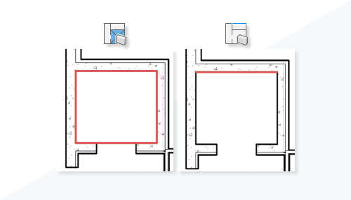
- Pick a closed area formed by room-bounding walls and columns, enabling new walls within this room to be created with one click.
or
- Pick existing segments of walls and columns to create new walls.
Newly created walls will be adjacent to the targeted wall or column face, improving efficiency and productivity in creating multiple walls for core and finish.
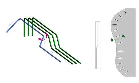
Parametric Rebar Crankin
Easily model cranked rebar in congested areas to prevent clashes.
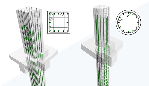
- You can propagate rebar with cranks to similar concrete elements.
- Like hooks, the crank is a parametric termination of the bar.
- You can add cranks to shape driven and free-form rebar.The presence of the crank defines the shape, either matching to an existing one or creating a new shape.
- The crank is added within the length of the segment for both shape-driven and free-form rebar.
- Editing constraints of bars with crank: For each cranked bar end, there are three handle positions from which the offset is measured:
- Crank and hook rotation: Crank rotation is applied to all bars in the set and defines the rebar shape. Rotate individual bars using Edit Bars. For free-form rebar, the crank default rotation (0 deg) is perpendicular to the host surface.
- Crank dimensions and override by type: Duplicate an existing crank type to create your own. Override the values of crank slope and lengths for the rebar type.
- Reporting cranked rebar lengths and editing the rebar shape family:
- Control the assignment of hooks, end treatments and cranks from the Type At Start / Type At End parameters in the rebar shape family.
- Use the new Shape Name parameter to report the shape code for cranked bars and sketched bars. The parameter is editable from the shape family.
- Add the start / end crank lengths to the rebar shape parameters for reporting in the model.
- Shape Name is read-only in the model.
Quick Access to Analytical Model Automation
Quickly and intuitively access and use analytical model automation, and customize the automation if needed.
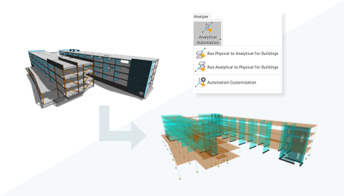
 Run Physical to Analytical for Buildings: This is a “one-click” Analytical Model Automation process.
 Run Analytical to Physical for Buildings: Select only the physical elements and click Run.
 Automation Customization: Customize the automation if needed.
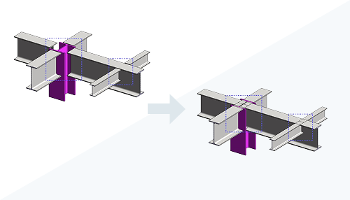
Custom Steel Connections Enhancements
Modify connections and object properties of the custom connection template.
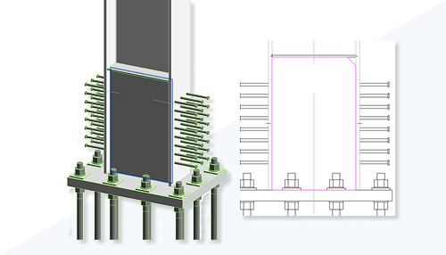
- You can move standalone elements inside custom connections while in edit mode.
- You can use the sketch editor for plates and bolt/hole/anchor/shear stud patterns in the custom connections while in edit mode.
- You can modify element properties in custom connections while in edit mode.
- During Edit Mode / Add elements, selection is constrained and will not work on elements not related to the custom connection.
- You can edit elements associated with the input elements of the custom connection as before.
- Removing elements from a custom connection will no longer delete them from the model. The connection will update without them, and those elements remain as standalone objects.
- Edit type for standard connections inside custom connection is no longer available from outside the edit mode. To change those connections, use Modify Parameters while inside the template edit mode.
- The steel profile type for beams inside custom connections cannot be edited from the template editor.
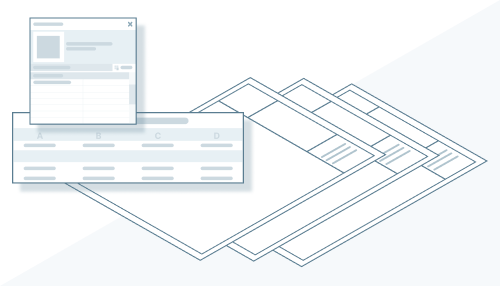
View to Sheet Positioning & Automated Placement
Use the Positioning & View panel under the Modify | Viewports to save, revise and manage view positions on a sheet.
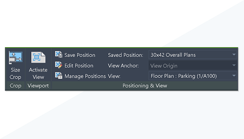
To align views across sheets, use the View Anchor options:
- View Origin (default): to pin and maintain view positions on sheets relative to the View Origin. This method is useful when you want to align plan orientation views between sheets.
- Center / Top Left / Top Right / Bottom Right / Bottom Left options, to pin and maintain view positions on sheets relative to the specified View Anchor. This method is useful when you always want views to be positioned at a specific location on the sheet, such as near a title block corner.
View to Sheet Positioning is useful for cases where you have numerous similar plan orientation views, and you want them to align and stay coordinated between sheets. Or you have typical layouts, such as building wall sections, that you want to be placed at the same offset for multiple sheets.
The existing Swap View on Sheet functionality has been integrated into these workflows as follows:
- The legacy Viewport Positioning parameter has been merged with the View Anchor parameter.
- View Anchor = View Origin is the default for all views.
- Views with the crop region supported and enabled can use View Anchor = Center, as well as the same additional new anchor options Top Left / Top Right / Bottom Right / Bottom Left.
You can swap views assigned to a Saved Position. A prompt to disable the position displays, and you can unassign or re-assign Saved Positions at any point.
A new supporting command, Reset Title Block Positions, has been added in the right-click menu of Sheets in the Project Browser, to move the placed title block instances on sheets back to the default origin. This command is available when multiple title block instances, or multiple sheets from the project browser are selected.
Coordination Model Enhancements
The Coordination model feature has been enhanced including graphical appearance, element visibility, and the ability to locate and view coordination models directly in the Revit canvas.
Graphical appearance
You can assign a color to each coordination model to quickly distinguish between different models,
You can also use distinctive colors for each category of coordination model elements for easier recognition.
Objects Visibility Control
You can manage the visibility of coordination models and their instances from the Visibility/Graphic Overrides for 3D View: {3D} dialog.
You can select only the relevant details to display by instantly hide elements or categories of elements using the contextual menu in the Modify | Coordination Model tab, or in the right-click menu.
Use the Modify | Coordination Model tab Revel Hidden Elements panel Toggle Reveal Hidden Elements Mode to reveal hidden coordination model elements and categories.
Show Option for Coordination Models Enabled
In the Manage Links dialog, click Show on the upper menu to locate and view coordination models directly in the Revit canvas. Alternatively, right-click the selected model in the list.
Sheet List Schedules Enhancements
Sheet List Schedules have been enhanced:
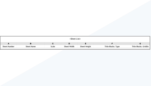
- Scale, Sheet Width, and Sheet Height parameters are now available in Sheet List Schedules.
- Title Block category, built-in and shared parameters can now be included in Sheet List Schedules. Shared parameters in Title Blocks behave like other family categories (they do not need to be bound to the project).
- A new Primary Title Block parameter is available on every Title Block instance in the project, which determines where the schedule pulls Title Block parameters from:
- It is checked (read-only) for sheets containing a single Title Block.
- It is modifiable for sheets containing multiple Title Block instances; only one instance can be checked.
Browser Organization for Panel Schedules
You can now organize Panel Schedules in the Project Browser through sorting, filtering, or grouping.
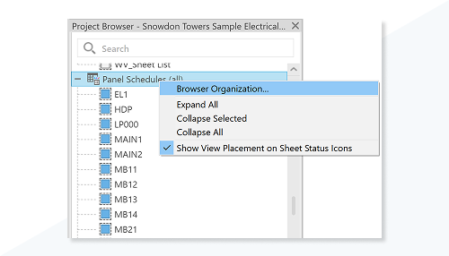
The Panel Schedules show the Panel Name under the Identity Data category.
Steel Plate Default Material
Newly created steel plates will have a meaningful material automatically assigned when created manually or by a steel connection.
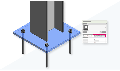
The default material of newly created steel plates depends on the unit chosen for Length in Manage Project Units.
- If imperial units (e.g., inches) are selected, the default material for newly created steel plates is Steel ASTM A36.
- If metric units (e.g., millimeters) are selected, the default material for newly created steel plates is Steel, S 235.
If the default material is not loaded into the model, the steel plates will have the first steel material that is loaded into the model (e.g., Metal Stud Layer).
Model Upgrade to Revit 2026
If the appropriate materials for metric or imperial models (Steel ASTM A36 / S 235) are loaded while upgrading the project file to Revit 2026, existing or new plates will behave as follows:
- Individually created plates with default/unchanged material (e.g., Metal Stud Layer) in previous releases: on upgrade, the material remains the same.
- Individually created plates with a modified material (e.g., Grade 80) in previous releases: on upgrade, the material remains the same.
- A plate from base plate connection with default material (e.g., Metal Stud layer) in previous releases: on upgrade, the material is changed to the default Steel ASTM A36/ Steel, S 235.
- A plate from base plate connection with modified material (e.g. Grade 80) in previous releases: on upgrade, the material remains the same.
- An individual plate from a custom connection with default/unchanged material (e.g., Metal stud layer) in previous releases: on upgrade, the material remains the same.
- An individual plate from a custom connection with a modified material (e.g., Grade 80) in previous releases: on upgrade, the material remains the same.
- A plate from a base plate connection nested in a custom connection with default material (e.g., Metal Stud layer) in previous releases: on upgrade, the material is changed to Steel ASTM A36/ Steel, S 235.
- A plate from a base plate connection nested in a custom connection with modified material (e.g., Grade 80) in previous releases: on upgrade, the material remains the same.
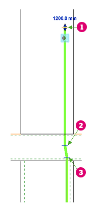
Point to Point Steel Modeling
Use the new global option in Structural Settings to create steel element geometry starting from the exact start and end click point.
This option is available if you check Manage Tab Structural Settings panel  (Structural Settings) Structural Steel Settings tab Automatic Shortening Disable automatic shortening of steel elements during auto-join.

- Point-to-point modeling defines precise geometry allowing you to visually check the correctness of steel elements.
- The new global option will also retroactively change the geometry of all steel elements of the existing project.
- Point-to-point modeling doesn’t change auto-join behavior.
The option is available for :
- Structural Steel Framing
- Structural Steel Columns
- Structural Steel Truss
- Beam systems using Steel sections
- Bracings using Steel elements
The Length parameter was moved to the Dimensions category in the Properties palette and renamed to System Length to better reflect that this is the analytical length, the theoretical distance between the two points used to create the member. The length of the physical element will continue to be displayed with the Cut Length parameter which takes into account any geometry changes to the member length.
This change is valid for all structural members.
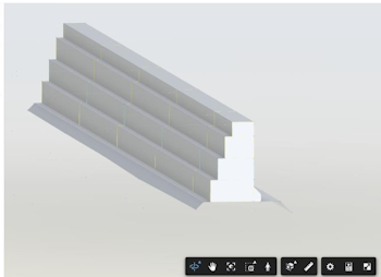
Slanted Column Behavior and Workflow
This workflow update enhances the reliability of parameters.
When you add a slanted column using the point-to-point workflow, the column’s geometry now extends to the end point of the system length.
If you turn off the point-to-point option, the slanted column will adjust to a secondary state. In this state, the column aligns with the bottom of the intersecting beam and attaches to the smallest intersection line. This differs from the default behavior that trims the face tangent to the beam.
Title Block Scale Override
Define an override value for sheet scale when different scale views are placed on the same sheet.
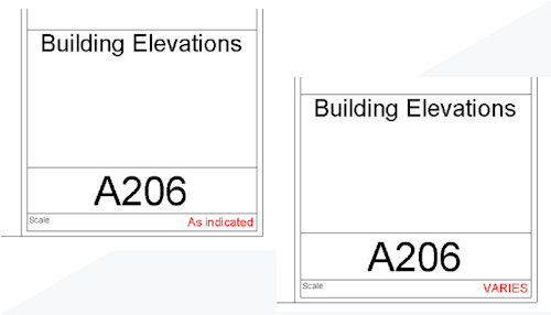
When a sheet contains multiple views of differing scales, set a value for the title block type parameter Scale Override (Multiple Values). The scale value override parameter can only contain text, numeric values are not supported.
Customize Layer Priority in a Compound Structure
You can now customize the layer priority independently from the layer function, from the element type level for all multi-layer elements, including walls, floors, roofs, ceilings, slabs, and toposolids.
The layer function and layer priority are no longer defined in a single setting.
IFC Link Enhancements
Performance and accuracy of placement is greatly improved when linking IFC files.
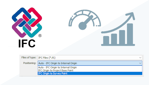
Linking IFC files into your models is now significantly faster than in previous releases of Revit. Additionally, you have increased control when linking an IFC model. In the linking dialog, use the drop-down list to select a positioning option. IFC links can be positioned at the same datum and orientation as allowed during export. The default position places the link’s origin at the internal Revit origin.
Copy/Paste Shape Editing
Points and lines used to shape-edit elements, toposolids, roofs, or floors can be copied and pasted.
In previous releases, you could not copy and paste points and lines when shape editing. This functionality is now enabled. Use the controls on the ribbon to copy and paste points and lines while in edit mode, or use the keyboard shortcuts Ctrl+C and Ctrl+V.
Enhanced System Zones
Create system zones for analysis by selecting spaces or sketching a boundary.
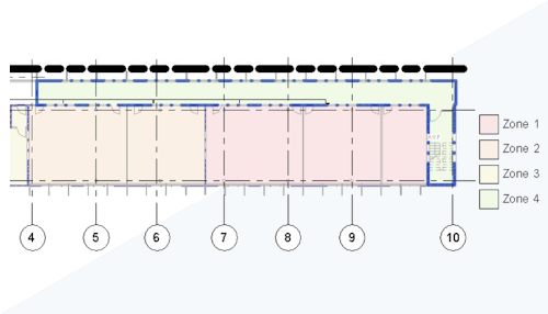
HVAC Zones and System Zone workflows have been consolidated into System-Zones. You can create zones by selecting spaces or by sketching. New instance properties have been added to zones to facilitate analysis. Assign types to System-Zones to easily create similar zones. Space-based zones can be converted to sketch-based zones, allowing the zone to be detached from the architectural model. Schedule System-Zones in schedules, or use embedded schedules to show how spaces and analytical spaces are related to the zone. System-Zones support the use of color schemes for illustrating your designs.
Dynamo Updates 3.4.1
Dynamo 3.4.1 introduces an extension for monitoring graph performance, version compatibility information in Package Manager, PythonNet3 for developers, and more.
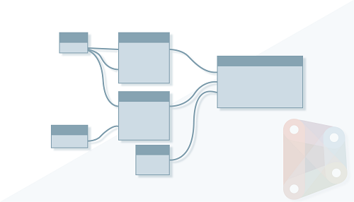
Highlights include:
- Improved TuneUp extension for monitoring graph performance: TuneUp is a profiling extension that logs how long each node takes to run and displays this information in a sidebar. This allows you to identify problem areas to optimize graph performance and understand which operations take the most time to execute. TuneUp is available as a built-in extension. Access TuneUp in the Extensions menu in Dynamo.
- Package Manager includes version compatibility information: Package authors can add version compatibility information to their packages on the Dynamo Package Manager website. This allows you to identify versions that are compatible with your setup. The Install button defaults to a compatible version, if one is available.
- PythonNet3 package available in Package Manager: The new PythonNet3 engine in Dynamo allows independent updates without waiting for new Dynamo or Revit releases. It improves .NET compatibility, supports LINQ and C# operators, fixes iterable detection, and updates key packages like NumPy and pandas, though some scripts may need adjustments due to breaking changes. After installing the package, you can set the Python engine for Python Script nodes by double-clicking the node and selecting the engine from the drop-down menu, or from the Node Options (three dots) menu Python Engine Version.
- Help documentation: Help documentation is available for 200 additional nodes.
- CSI reference values removed from Revit content files: Starting in Revit 2026, sample files no longer include parameter values for OmniClass Number, OmniClass Title, Keynote, Assembly Code, and Assembly Description. As a result, Dynamo for Revit sample graphs that include these parameters have been updated. Graphs reading these parameter values will now return empty results, which may affect subsequent nodes in your workflow. To ensure they continue working as expected, review and update any nodes that rely on these values.
- Length parameter renamed to System Length: The “Length” parameter has been renamed to “System Length” for Structural Steel Framing elements (beams and columns). To maintain functionality, adjust any graph that relies on this parameter name (for example, using the Element.GetParameterValueByName API method).
- Removed and deprecated nodes: Several nodes have been removed and deprecated.
Additional enhancements
Show Imported CAD Files in the Manage Links Dialog
The Manage Links dialog shows the imported DWG, DXF, DGN, SKP, and AXM CAD formats for both projects and families.
You can identify the corresponding linked files by the Status and Reference Type properties in the respective columns. To choose Remove and Show the imported CAD files, use either the upper menu or right click.
Show Start and End of Bar
Add hooks, end treatments, or cranks to bar ends more intuitively.
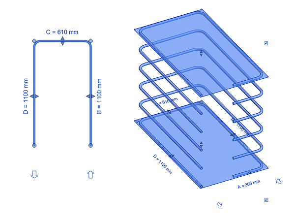
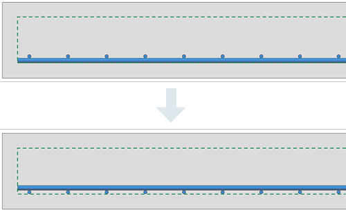
Control Fabric Sheet Wires Position at Cover
Precisely position fabric sheets and custom fabric sheets at the concrete cover.
User Profile Update Reminder
A Profile dialog displays the first time you open Revit after it has been installed. It shows questions about the discipline and job role for which you use Revit.
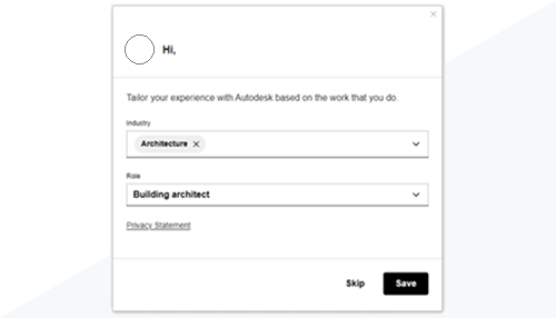
If you choose to skip the update, the dialog reappears after 60 days. This reminder will be displayed no more than twice a year.
Skip the Creation of Backup Folder for Links
When linking worksharing enabled models, the creation of a backup folder is no longer required.
Previously when a worksharing enabled model was linked a _backup folder was created on the local computer. To speed the linking process and the opening of models with linked files, the creation of this folder is no longer required. This enhancement also supports workflows using Desktop Connector when you have limited permissions.
Next Generation Insight
The next generation of Autodesk Insight is now installed when Revit is installed.
Previously Autodesk Insight required the installation of an add-on. Autodesk Insight is now installed automatically. To access it, click Analyze tab  Carbon Insight Panel
  (Analyze).
Tag/Schedule Part Type and Distribution System
Part Type and Distribution System parameters can now be tagged and scheduled in your models.
To enhance your abilities to document your models, you can now tag and schedule Part Type and Distribution System parameters. These parameters can also be used to filter and sort in schedules, making them more readable and organized.
MEP Categories Display Improvements
Additional MEP categories now display consistently with other MEP categories in MEP discipline views.
The following categories now display consistently with other MEP categories in views using the MEP discipline.
- Food Service
- Medical Equipment
- Fire Protection
- Audio Visual Devices
- Signage
Apparent Power Calculations Enabled for Analytical Loads
Set calculations to use apparent power for analytical loads.
Analytical loads assume 1.0 power factors regardless of specified values.
Circuit, Spare, and Space Design Continuity
Spares and spaces on a panel schedule now belong to the Circuit category.
Circuits, spares, and spaces are all included in the Circuit category. Naming schemes and parameters are applied to all three in the same way. Spares and spaces are included in circuit schedules so the properties of these items can be seen alongside the circuits. Spares can be edited to add connections. When circuits are converted to spares or spares are converted to circuits, inputs are preserved, and load names and circuit states are updated. Spares can be disconnected and reassigned to other panels.
Improved Electrical Circuit Path
Circuit paths are connected to the correct locations on nested equipment.
When a circuit path is created, the path and the home run will be connected to the location of a connected nested family. Circuit boundary lines, generated home run wires, and circuit pathways all point to the location of the nested electrical panel.
Steel Specific Parameters for Shape-Driven Families
The Exact Weight and Paint Area parameters are now available for structural steel elements.
- You can find these parameters for any steel elements created using a Revit shape-driven family.
- This aligns the availability and calculation method of these parameters with the existing Paint Area and Exact Weight parameters on steel fabrication elements.
- Exact Weight: This parameter outputs the exact weight of the element by taking into account any cuts, copes, shortens, etc. The formula used is Volume multiplied by Material Density.
- Paint Area: This parameter outputs the total outer surface of the element, used to calculate the paint quantity estimates. The formula used is Perimeter multiplied by Cut Length.
- For hollow profiles, the value will only consider the outer area of the section.
- Inner openings or copes/skewed cuts at the element ends are not subtracted from the displayed paint area, as the formula uses only the Cut Length for generating the painted area of the element.
Enhanced Family Substitution for Twinmotion for Revit
Asset substitution from Revit to Twinmotion has been enhanced:
- All the Revit model categories have been enabled for Twinmotion substitution.
- An editable dynamic substitution path has been enabled for storing the downloaded assets.
To edit the location where you want to store them, open the Revit model, then go to File Options File Locations Places Twinmotion Substitution entry, and change the library path as desired.
Relocate Options and Properties for Wall-Related Functionalities
The following controls have been moved from the Options Bar to the ribbon:
| Attach Wall Top | Select Wall Attach Top/Base |
Modify | Walls tab Modify Wall panel Attach |
| Attach Wall Base | Select Wall Attach Top/Base |
Modify | Walls tab Modify Wall panel Attach |
| Detach Wall from Selected Elements | Select Wall Detach Top/Base |
Modify | Walls tab Modify Wall panel Detach Top/Base |
| Detach Wall from All | Select Wall Detach Top/Base |
Modify | Walls tab Modify Wall panel Detach All |
| Configure Wall Joins | Modify Wall Joins Select Wall Joins in Canvas |
Modify | Wall joins tab Configuration panel Buttons: Previous, Next, Square Off, Butt, Miter |
| Allow/Disallow Wall Joins | Modify Wall Joins Select Wall Joins in Canvas |
Modify | Wall joins tab Display panel
Buttons: Allow Join, Disallow Join |
| Wall Join Display Setting | Modify Wall Joins Select Wall Joins in Canvas |
Modify | Wall joins tab Display panel Display |
| Modify Sweep Returns | Select Sweep Modify Returns |
Modify | Wall Sweeps tab Return Options panel
Buttons: Straight Cut, Return, Angle |
| Modify Reveal Returns | Select Sweep Modify Returns |
Modify | Reveals tab Return Options panel
Buttons: Straight Cut, Return, Angle |
| Modify Sweep/Reveal Returns Embedded in Wall Type | Select wall with embedded sweep/reveal in wall type Modify Returns |
Modify | Walls Return Options panel
Buttons: Straight Cut, Return, Angle |
Relocate Controls from Options Bar to Ribbon for Tags and Modify Tools
The following controls have been moved from the Options Bar to the ribbon:
| Tag on Placement | When placing a window, door, wire or duct, the Orientation, Leader line, and Leader Length controls are placed on the contextual tab of the ribbon. | Modify | <Element> tab Tag panel. |
| Tag by Category | The Orientation, Angle, Leader Line, Leader Type, and Leader Length controls display on the contextual tab of the ribbon. | : Modify | Tag panel Tags and Placement panels. |
| Move | The Multiple button is placed on the contextual tab of the ribbon. | Modify | Move tab Move panel |
| Copy | The Copy button is placed on the contextual tab of the ribbon. | Modify | Copy Copy panel |
| Mirror | The MIrror button is placed on the contextual tab of the ribbon. | Modify | Mirror tab Mirror panel |
| Rotate | The Place button is placed on the contextual tab of the ribbon. The Angle text box is only activated after the first ray of rotation is placed. | Modify | Rotate tab Rotate panel |
| Array | The Linear, Radial, Group and Associate, Place buttons are placed on the contextual tab of the ribbon. The Place center of the rotation is set as default. | Modify | Array tab Array panel |
| Label | The Type button in the Labeling panel allows you to know and change the parameter’s type for labeling. | Modify | Array tab Labeling panel |
Relocate Options and Properties for Dimension Functionalities
Several options were moved from the Options Bar to the ribbon or Properties Palette.
| Create Aligned Dimension: Prefer, Pick, Baseline Offset, Options | Ribbon: Modify Measure Aligned |
Ribbon
Modify | Place Dimensions tab |
| Create Linear Dimension: Baseline Offset | Ribbon: Modify Measure Linear |
Ribbon
Modify | Place Dimensions tab |
| Create Angular/Radial/Diameter/Arc Length Dimension: Prefer | Ribbon: Modify Measure Angular/Radial/Diameter/Arc |
Ribbon
Modify | Place Dimensions tab |
| Create Spot Elevation: Leader, Shoulder, Relative Base, Display Elevations | Ribbon: Modify Measure Spot Elevation |
Ribbon
Modify | Place Dimensions tab |
| Create Spot Coordinate: Leader, Shoulder | Ribbon: Modify Measure Spot Coordinate |
Ribbon
Modify | Place Dimensions tab |
| Create Spot Slope: Slope Representation, Offset from Reference | Ribbon: Modify Measure Spot Slope |
Ribbon
Modify | Place Dimensions tab |
| Modify Linear/Angular/Radial/Diameter/Arc Length Dimension: Prefer | Select dimension | Ribbon
Modify | Place Dimensions tab |
| Modify Linear Dimension: Leader, Baseline Offset | Select dimension | Properties Palette |
| Modify Angular/Radial/Diameter/Arc Length Dimension: Leader | Select dimension | Properties Palette |
| Modify Spot Elevation: Prefer | Select Spot Elevation | Ribbon
Modify | Place Dimensions tab |
| Modify Spot Elevation: Leader, Shoulder, Relative Base, Display Elevations | Select Spot Elevation | Properties Palette |
| Modify Spot Coordinates: Prefer | Select Spot Coordinates | Ribbon
Modify | Place Dimensions tab |
| Modify Spot Coordinates: Leader, Shoulder | Select Spot Coordinates | Properties Palette |
| Modify Spot Slope: Prefer | Select Spot Slope | Ribbon
Modify | Place Dimensions tab |
| Modify Spot Slope: Slope Representation, Offset from Reference | Select Spot Slope | Properties Palette |
| Show Related Dimensions | Family editor Select a dimension that is related to other dimensions |
Ribbon
Modify | Dimensions tab |
Updated Design Codes in Robot Structural Analysis
The following design codes have been updated:
- Steel design
Eurocode:
- EN 1993-1-1:2022 (General rules and rules for buildings)
- EN 1993-1-2:2024 (Structural fire design)
- EN 1993-1-3:2024 (Cold-formed members and sheeting)
- EN 1993-1-5:2024 (Plated structural elements)
India:
- IS:800:2007 – amendments 2012 & 2024
- Implementation of complex section design
Australia:
- AS 4100:2020 Amd1:2021
2. Seismic analysis
Canada:
- NBC 2020
India:
- IS 1893 Part 1 with amendments
Eurocode:
- NS-EN 1998 NA 2021
Australia:
- AS 1170.4:2007 (AMD 2:2018)
3. Load Combinations
Eurocode:
- EN 1990:2023
INDUSTRIES: Architecture, Buildings, Civil Engineering, Civil Infrastructure, Construction, Interior Design, MEP Engineering, Structural Engineering