


MEP toolset is included with AutoCAD
By Microsol Resources, Graitec Group | CAD
HVAC and building systems are made easy with an industry-specific toolset for MEP (mechanical, electrical, and plumbing) that increases productivity by up to 85%.* With the MEP toolset, you can access our library of 10,500+ intelligent MEP objects, optimize your workflow with individual palettes and domain-specific ribbon and automatically update drawings, sheets, and schedules when changes occur.
10,500+ intelligent MEP objects
Use an extensive library of objects that represent the real-world components in mechanical, electrical, and plumbing systems to assist you in your design needs.
AutoCAD MEP 2022 toolset is an object-based CAD application. When you design in the application, you use large collections of objects that represent the real-world components in mechanical, electrical, and plumbing systems. Examples of these objects include segments of duct, pipe, cable tray, and plumbing lines; fittings of all types; and equipment—called multi-view parts or MvParts in the software—such as air handling units, electrical transformers, and drinking fountains.
AutoCAD MEP 2022 toolset objects are composed of lines, arcs and other standard AutoCAD objects, but they also contain information that allows them to function like the real-world components that they represent, to relate intelligently to one another, and to display in a 2-dimensional (2D) or 3-dimensional (3D) context. The objects have specially designed connection points called connectors that enable them to connect intelligently to appropriate objects and transfer information, such as shape, size, and system.
As an example, you can insert a variable air volume (VAV) box into an HVAC system drawing, and then draw a duct from one of its connectors. When you draw the duct, the software detects the size and shape of the connector on the VAV box and draws an appropriate duct segment as shown.
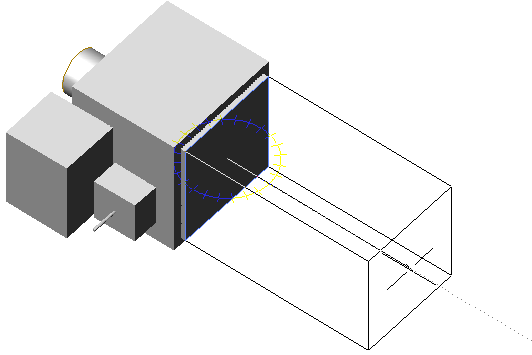
Drawing duct from a VAV box
To continue the example, you can draw and connect additional duct segments, fittings, and HVAC equipment that are all intelligently connected in the same manner. As you do so, the software inserts and adjusts the objects in the run to maintain their connectivity. For example, it inserts appropriately-sized fittings as you lay out duct segments. It also inserts an appropriately-sized transition fitting if you change the size of a segment.
The ability of the software to detect the attributes of objects and act accordingly to maintain the connectivity of the system is an important aspect of the software. It enables you to design fully connected systems quickly and preserves their connectivity when you modify them.
MEP workspaces
MEP-specific workspace environments include individual palettes and domain-specific ribbons to optimize your workflow tasks and save you time.
Out of the box, AutoCAD MEP 2021 toolset contains tools geared to mechanical, electrical, and plumbing professionals in the building industry. The workspace environments (electrical, HVAC, piping, plumbing, and schematic) include individual palettes and domain-specific ribbons to optimize your workflow tasks.

Duct system in AutoCAD MEP 2021 toolset HVAC workspace
The tool palette includes parts related to the current domain. You can define tool properties from the tool or properties palette. You can also customize the tool palette to include unique tools commonly used in your company’s engineering designs.
Automatic object updates
Drawings, sheets, and schedules can be automatically updated when changes occur, making it easy to minimize errors. You can also match the properties of other objects. Activate or deactivate this feature to your preference and project needs.
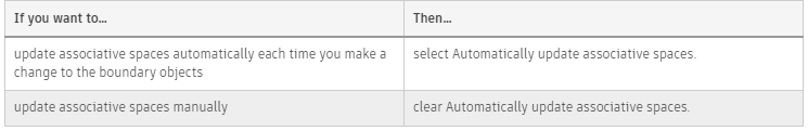
Use this procedure to activate or deactivate the automatic update of associative spaces.
Updating each temporary change to the space geometry might not be necessary or desirable. For example, if you delete a wall only to replace it with a different one in the same position, you only need the space to update after the new wall is in place, rather than once when the old wall is removed and again when the new one is inserted.
Manual updates offer better performance, but mean that the geometry of spaces and their boundary objects might be out-of-synch at a given time during the drawing session.
When the automatic update of associative spaces is deactivated, and an area calculation standard has been selected to calculate boundary offsets, the rules of the standard will only be applied to changed spaces when either the automatic update has been activated again or the spaces are updated manually.
- Click

 Options.
 - Click the AEC Object Settings tab.
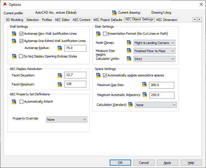
- Under Space Settings, specify whether associative spaces will be updated automatically:
- Click OK.
Tip: The automatic update of spaces can also be turned on or off via the aecspaceautoupdate command.
Drawing version management
Check out and check in files to maintain versioning, prevent unauthorized modifications, and ensure drawing integrity. Easily revert to an earlier version of your drawing at any time.

Project Navigator allows drawing versioning for AutoCAD Architecture 2022 toolset and AutoCAD MEP 2022 toolset drawings. This ensures informed collaboration between multiple users and prevents unauthorized modifications to the drawings.
When a project involves multiple users working together on a set of drawings, it is essential to have a file locking and versioning mechanism to ensure that all changes are recorded and there are no access clashes. When you check out a drawing from the Project Navigator, other users only have read-only access to the drawing and can view the last saved version of the drawing, till you check the drawing back in. This ensures that there are no file access conflicts and each modification made to a drawing is recorded.
Changes being made to the checked out drawing are not dynamically visible to other users and as the checked out file is saved, no xref notifications are sent to others which can be an interruption to their work.
Hovering over a file in the Project Navigator shows you the status of the file, the name of the drawing, its location, the size of the file, the date and time the file was last checked in, the name of the user who last checked-in the file, and the check in version history with the check-in comments. Red checkmarks indicate that the drawing is checked out by another user, and a green checkmark indicates that the drawing is checked out by you.
When you check out a file, make modifications and check it back in, you are prompted to add comments on the changes you have made. This information is displayed in the Check-In Version History, along with your user name, your domain or computer name, and the date and time of the check-in.
Every time you check-in a file, AutoCAD Architecture 2022 toolset creates a backup file in the same folder where the drawing is stored, with the drawing name appended with check in time. If during the course of a project, you wish to revert to an earlier version of the drawing, the comments history makes it easier for you choose the backup file version you wish to roll back to.
Designing with space and zone objects
Enhance your design options by using spaces to organize reports and zones to structure spaces into various groups, according to different schemes.
Zones are used to group spaces and subordinate zones.

Support for layer standards
Incorporate common layer standards into your project standards, customize them, or create your own.
Layers organize the objects in a drawing and enforce linetype, color, and other standards. They are the equivalent of the overlays used in paper-based drafting. For example, in paper-based drafting, a building plan might contain overlays for the foundation, floor plans, and mechanical, plumbing, or electrical layouts. In AutoCAD MEP 2022 toolset, you can organize the same information on layers in your drawings.
Layer standards establish naming conventions for the layers in your drawings. A layer standard contains rules that determine the structure of the layer names in a drawing. You can use layer standards to enforce and manage project standards for layers.
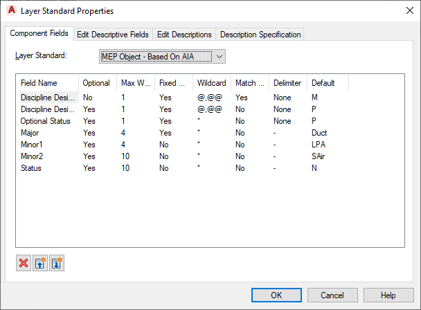
The software provides several default layer standards based on industry-standard layering conventions (for example, MEP Object – Based on AIA, and BS1192 – AUG Version 2). When you create a layer based on a layer standard, the name of the layer has several parts separated by delimiters, such as hyphens. Each part of the name is determined by the rules that are set in the layer standard definition. The default layer standard definitions for AutoCAD MEP 2022 toolset are based on common industry layer standards. For example, according to the MEP Object layer standard, the layer name for duct is M-Duct-Std.
You can incorporate the default layer standards into your project standards, customize them, or create your own.
Display System
With the Display System, you only have to draw an object once. The appearance of that object will change automatically to meet the display requirements of different types of drawings, view directions, and levels of detail.
The display system in AutoCAD Architecture 2022 toolset is designed so that you only have to draw an architectural object once. The appearance of that object then changes automatically to meet the display requirements of different types of drawings, view directions, or levels of detail.
Display Properties and Display Components
The view-dependent display of objects in AutoCAD Architecture 2022 toolset is made possible by a hierarchical system of display settings that specify display properties (visibility, layer, color, linetype, and so on) for individual display components of all the different types of architectural objects under all the different viewing scenarios.
For example, a door object has 5 display components by default: Door Panel, Frame, Stop, Swing, and Glass. (Many display components correspond directly to the physical components of the object, but some, like Swing, do not.) For each of these display components, the drawing default settings specify the relevant display properties as appropriate for the drawing type. In the case of doors, the default settings specify that the Swing component is visible in plan and elevation views, but not in 3D views.
Overrides
The drawing default settings for a particular type of object apply to all such objects in the drawing, except those for which an override is in effect. For example, you can change a setting for all doors of a particular style (a style override) or for an individual door (an object override).
Establishing and Modifying Default Display Settings
If you are a CAD manager, you will want to fully understand the display system structure and the display manager so that you can modify and organize default settings as necessary to implement your own display standards. But any user can quickly change the appearance of an object in a particular view by modifying values on the Display tab of the Properties palette.
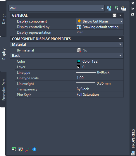
Display tab when display component is selected
To change the display using this tab, click ![]() (Select Components), select an object display component (like a hatch or a boundary), and then select or enter a new value for the display property you want to change (such as color, visibility, or lineweight).
(Select Components), select an object display component (like a hatch or a boundary), and then select or enter a new value for the display property you want to change (such as color, visibility, or lineweight).
The results are immediately visible in the drawing area for the current display representation and can be applied to other display representations that use the same component. You can also apply style or object overrides by changing the value of Display controlled
Detail Component Manager
Use the Detail Component Manager dialog box to seamlessly navigate between different detail component databases. A hierarchical tree view and a filter feature make it easy to locate individual components within a database.
Using the Detail Component Manager dialog box, you can navigate among different detail component databases. A hierarchical tree view and a filter feature make it easy to locate individual components within a database. Once you find the component you need, you can insert it into a drawing, or you can drag and drop it onto a tool palette for repeated use. Note that the five buttons arranged vertically in the middle of the dialog box are unavailable unless you have edit privileges for the selected database.
You can access the Detail Component Manager in the following ways:
- Click . Find
- Right-click any detail component insertion tool on a tool palette in the workspace, and then click Detail Component Manager.
- On the Tool Properties worksheet for a detail component tool, click the Select a Component icon on the Component line.
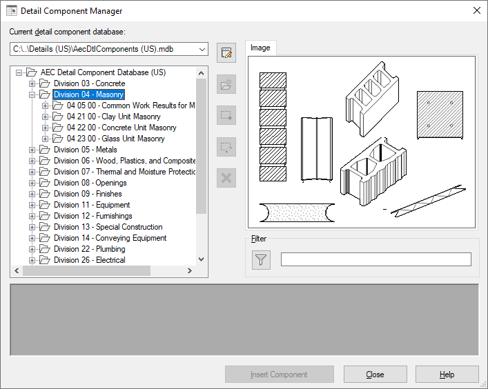
The Detail Component Manager dialog box
Need Autodesk AutoCAD support?
If you would like to purchase AutoCAD licenses or need support, please contact us at info@microsolresources.com. Our team will assist you in getting the assistance you need.
INDUSTRIES: MEP Engineering