


Mechanical toolset is included with AutoCAD
By Tom Schwarzweller | CAD
The Mechanical toolset (previously referred to as AutoCAD Mechanical), now included as part of the AutoCAD including specialized toolsets offering, can help save many hours of design and rework by automating many common tasks. Read more about this blog article that details the productivity gains that users may experience when using AutoCAD with the Mechanical toolset rather than just basic AutoCAD.
Increase productivity by up to 55% with industry-specific tools for mechanical engineering, including 700,000+ intelligent parts and features.
With the Mechanical toolset, you can: Access the library of standards-based parts, tools, and custom content; customize properties of object types and create them on custom layers; automate tasks such as creating bills of materials (BOMs). You can read the System Requirements for AutoCAD 2023 here.
Mechanical toolset features
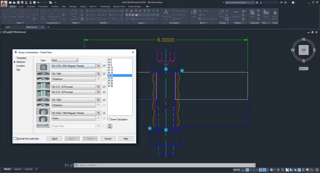
700,000+ standard parts and features
Produce accurate drawings with standard components to support ISO, ANSI, DIN, JIS, BSI, CSN, and GB standards. Create and save custom content through the Content Manager, which enables you to add a part or feature to a content library.
You can use one of the following ways:
- By adding the current drawing to a custom content library.
- By adding selected geometry to a custom content library.
- By adding a block to the content library
- By creating an item from scratch.
- By copying an item from a standard part library
The first 4 methods enable you to create items that do not exist in the standard part content library. The last method lets you create an item that is a variation of an existing standard part or feature. For example, a steel shape with chamfered edges. If the selection set you are adding as a new item contains parts or features inserted from a content library, they are ignored. However, if you explode them beforehand, they are not ignored.
For example, consider a drawing of a plate with a hole, where the hole was inserted from the standard part library. If you add the plate to a custom content library, the hole is ignored. However, if you explode the hole before you add the plate to the library, the hole is not ignored.
Customized layer management
Save time with commands that create mechanical layers—so you don’t have to do it manually. There are some significant differences between how you manage layers in AutoCAD and AutoCAD Mechanical.
AutoCAD commands always create objects on the current layer. As such you must set the layer corresponding to the object type as the current layer before you create the object. It also means that you must create the layers and specify settings such as color, line weight, and line type beforehand.
AutoCAD Mechanical commands, using a feature that is known as Automatic Property Management, are pre-configured to create objects on specific layers. Regardless of what layer is set current, these commands create geometry/objects only on the predefined layer. If the layer doesn’t exist, the command automatically creates the layer. Settings such as layer color, line weight, and line type are taken from a set of pre-configured settings that are referred to as layer definitions.
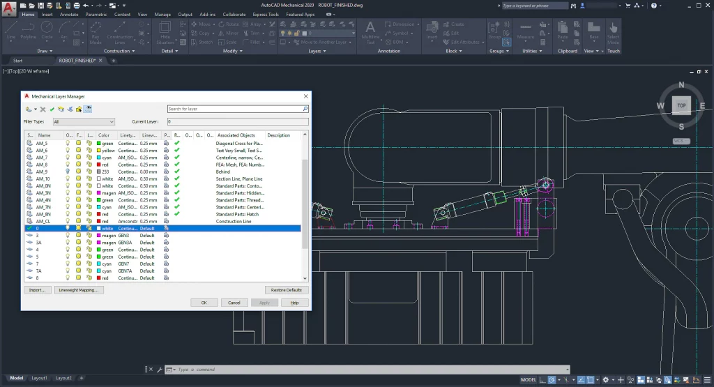
The layers that AutoCAD Mechanical creates on the fly are called mechanical layers. The AMLAYER command enables you to see a list of mechanical layers as well as layer definitions. Similar to how the LAYER command enables you to change the properties of a layer, the AMLAYER command enables you to change the properties of mechanical layers and layer definitions. Additionally, the AMLAYER command shows you what objects are created on each layer.
AutoCAD Mechanical ships with 31 layer definitions, which have been assigned to different objects by default. The names of these layers begin with “AM_”, followed by a number or a phrase as described below.
- Working layers: Layers AM_0 through AM_12. Almost all geometry is created on working layers.
- Standard part layers: Layers AM_0N through AM_12N. AutoCAD Mechanical commands create standard parts and features on these layers.
- Special layers: AM_BOR (used for drawing borders), AM_PAREF (used for part references), AM_CL (used for construction lines), AM_VIEW (used for viewports), and AM_INV (used for invisible lines).
AutoCAD Mechanical allows you to customize the properties of each object type so that AutoCAD Mechanical commands can create them on a layer of your choice instead of the ones they are created on by default.
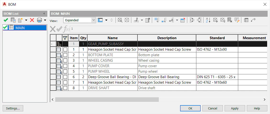
Bill of Materials
Use commands to automate mechanical engineering tasks and simplify your work. Gain more control over BOMs, part lists, associative balloons, and part references.
Power and automatic dimensioning
Get more work done in less time. Use abbreviated dialog boxes to set preferences for power dimension commands for the current standard.
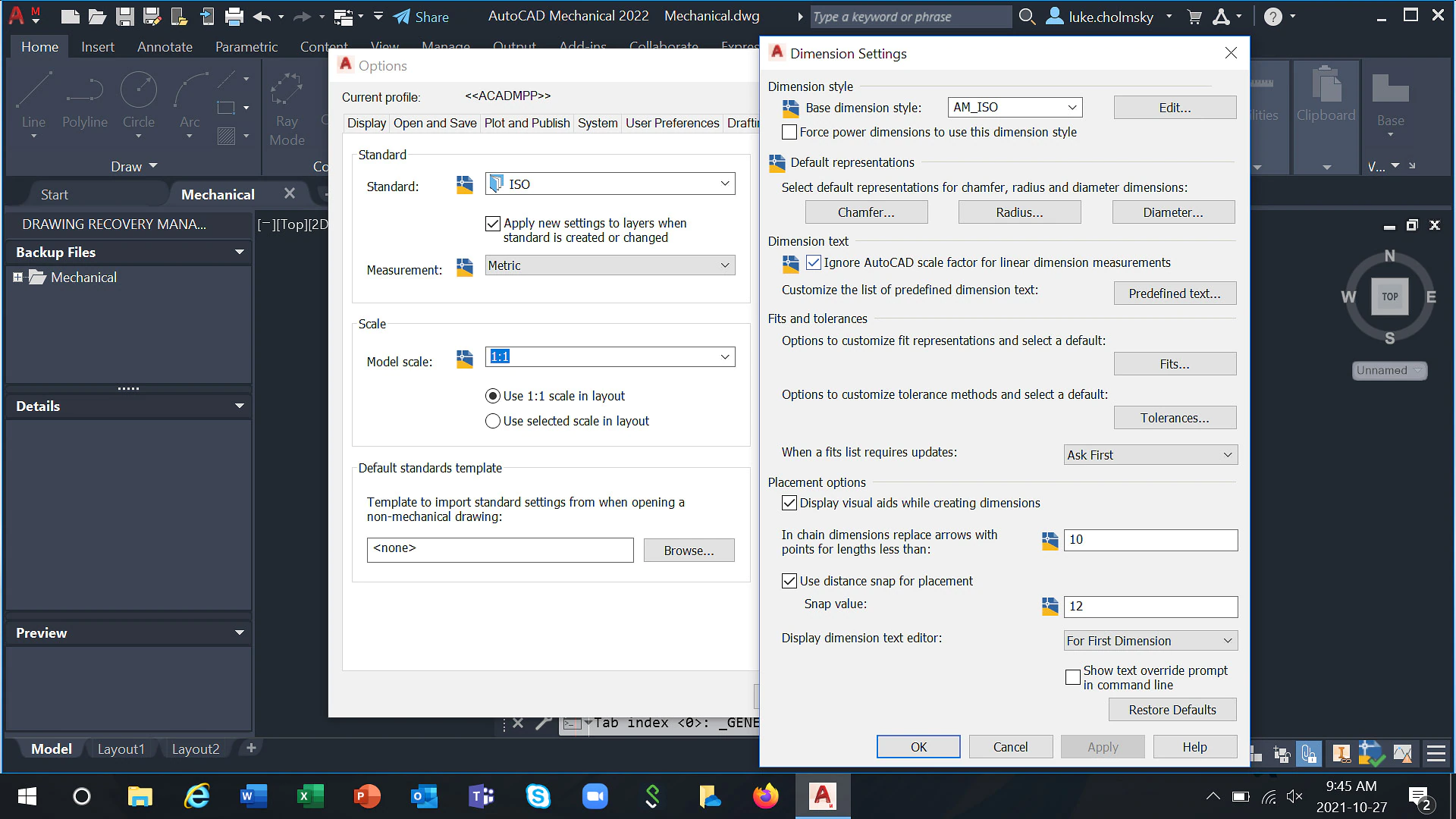
Use this dialog box to set preferences for Power Dimension commands for the current standard.
Dimension style
- Base dimension style: Sets the dimension style to be used as the base dimension style. All the dimension types are based on the dimension style or a variation (a sub-style).
- Edit: Displays the Dimension Styles dialog box, enabling you to create, modify, and assign dimension styles.
- Force power dimensions to use this dimension style: Prevents the dimension style from being overridden with the DIMSTYLE command.
Default representations
- Chamfer: Displays the Chamfer Representation dialog box, enabling you to select the default chamfer dimension representation from a predefined list of representations.
- Radius: Displays the Radius Representation dialog box, enabling you to select the default locations for dimension line, dimension text, and arrowhead for radius.
- Diameter: Displays the Diameter Representation dialog box, enabling you to select the default locations for dimension line, dimension text, and arrowhead for diameter.
Dimension Text
- Ignore AutoCAD scale factor for linear dimension measurements: Makes Power Dimensioning ignore the DIMLFAC system variable and other settings that control the linear scale.
AutoCAD Mechanical toolset uses several scaling mechanisms such as scale areas, detail views, and annotation views, that are not available in AutoCAD. Power dimensioning recognizes the scales and automatically compensates for them. If you choose to honor AutoCAD scale factors and use different scales in different places in a drawing, AutoCAD Mechanical toolset’s scaling mechanisms may not reflect the correct dimension value.
Note: This setting is not available for Inventor linked drawings.
- Predefined Text: Displays the Predefined Text dialog box, which enables you to create predefined dimension text templates for Power Dimensioning commands at draw time.
Fits and Tolerances
- Fits: Displays the Fits Representation dialog box, which enables you to set the default fit representation. It also provides access to the System Editor, which enables you to modify the Windows registry settings that define the existing fit representations as well as create new ones.
- Tolerances: Displays the Tolerance Representation dialog box, which enables you to set the default tolerance method. It also provides access to the System Editor, which enables you to modify the Windows registry settings that define the existing tolerance methods as well as create new ones.
- When a fits list requires updates: Configures how fits lists rebuild. You can choose to update fits lists schematically, have the system prompt you, or update fits lists on demand by selecting the manual option.
Placement Options
- Display visual aids when creating dimensions: Displays an icon on the crosshairs when a dimension is created, indicating the type of dimension being created.
- In chain dimensions, replace arrows with points for lengths less than Defines the distance at which arrowheads are replaced with points in chain dimensions.
- Use distance snaps for placement: Turn on distance snaps, which cause dimensions to snap into place as you move the dimension line in the drawing area.
- Snaps value: Sets the distance from the snap position to the object being dimensioned.
Display dimension text editor
Sets how often the dimension text editor appears during a command session.
Show text override prompt
Enables the display of the text override prompt enabling you to modify the dimension text on the command line during the dimensioning process. By default, this check box is cleared.
Restore defaults
Resets all settings to the factory settings for the current standard. If the current standard is a custom standard, the settings default to the factory settings of the standard it is derived from.
GD&T symbols/annotations
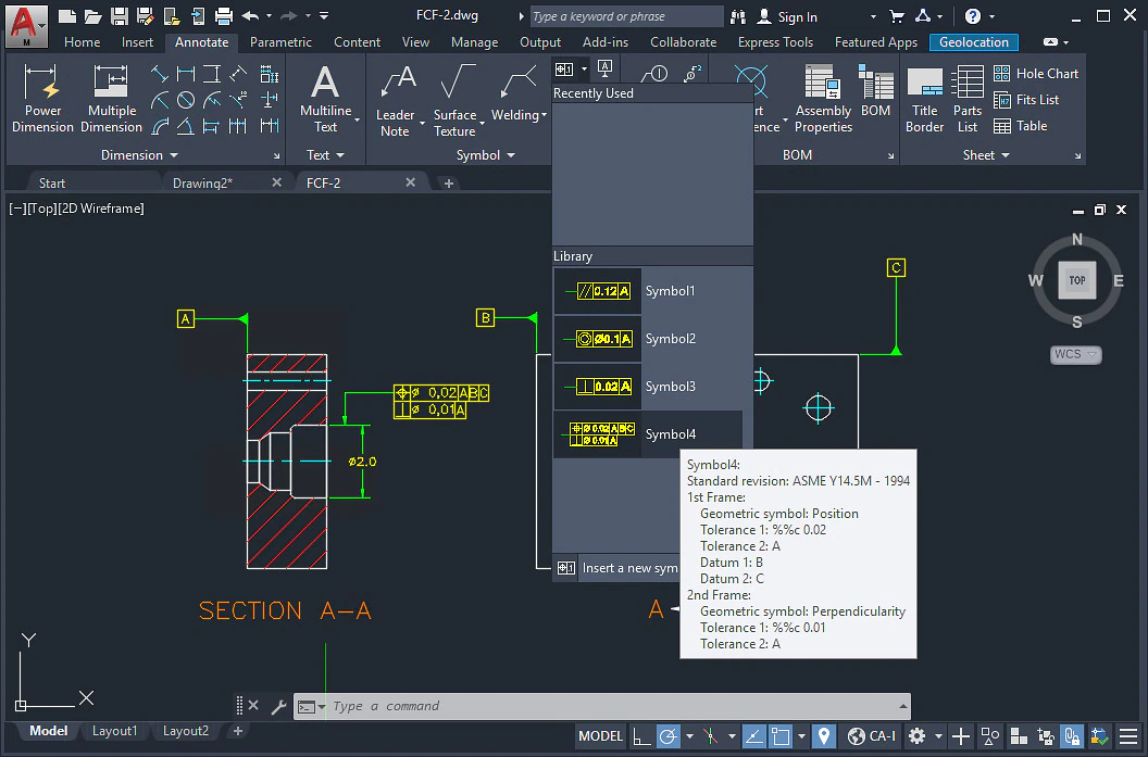
Pre-configure symbols and save them to the symbol library for reuse. You can also access symbol libraries for welding, surface texture, and more. The symbol library displays inside the dialog box that is displayed when you insert a symbol in a drawing. When you select a symbol from the symbol library, all other information you typically enter in the dialog box is filled automatically.
Some symbol libraries are available on the ribbon, making it easier to access them. What’s more, when you insert a symbol directly from the symbol library on the ribbon, AutoCAD Mechanical toolset does not display any dialog boxes.
The symbols with libraries that are accessible from the ribbon are:
- Surface Texture symbols
- Welding symbols
- Feature Control Frame symbols
- Edge symbols
- Leader note symbols
Note: The symbol library for leader notes has some differences from the symbol library for other symbols. Please refer the related concept “About Using Leader Note Templates from the Symbol Library” for details.
The symbols with libraries that are not accessible from the ribbon are:
- GOST Dead Joint symbols
The symbols that do not support symbol libraries are:
- Taper and slope symbols
- Datum Identifier symbols
- Feature Identifier symbols
- Datum Target symbols
- GOST Marking and Stamping symbols
When you add a symbol to the library, you are prompted to provide a unique name for it. If the name is longer than the available space, the name is truncated in the library. However, when you move the pointer over the name, the entire name appears in a tooltip. Additionally, the tooltip shows a summary of the settings for that item.
You can delete, rename, or modify a symbol in the symbol library, you can set one as the default. When you create a symbol without using the symbol library, the default settings for dialog boxes are derived from the default symbol. You can also opt not to have a default, in which case the rules of each individual symbol type control the default settings of the symbol.
You can import a symbol library from another drawing. However, the drafting standard and revision of the symbol you are importing must be the same in both drawings.
Note: You can import a symbol library of another revision (but same standard) providing the following conditions are met.
- The drawing you are importing from was last saved in a previous version of the AutoCAD Mechanical toolset.
- The current drawing does not contain the revision you are trying to import.
During the import process, you get to choose whether to replace the entire library, append symbols, or overwrite symbols. If you choose to replace it, AutoCAD Mechanical toolset deletes the current library and replaces it with the imported library. If you choose to append, imported symbols having the same name as existing symbols, are renamed by affixing a number to their name. If you choose to overwrite, imported templates replace the existing templates having the same name
Leader notes (AMNOTE)
Get the most out of your notes with formulas that automatically apply to an object. Use a template from a predefined set to display meaningful context-sensitive information immediately, instead of having to do it yourself.
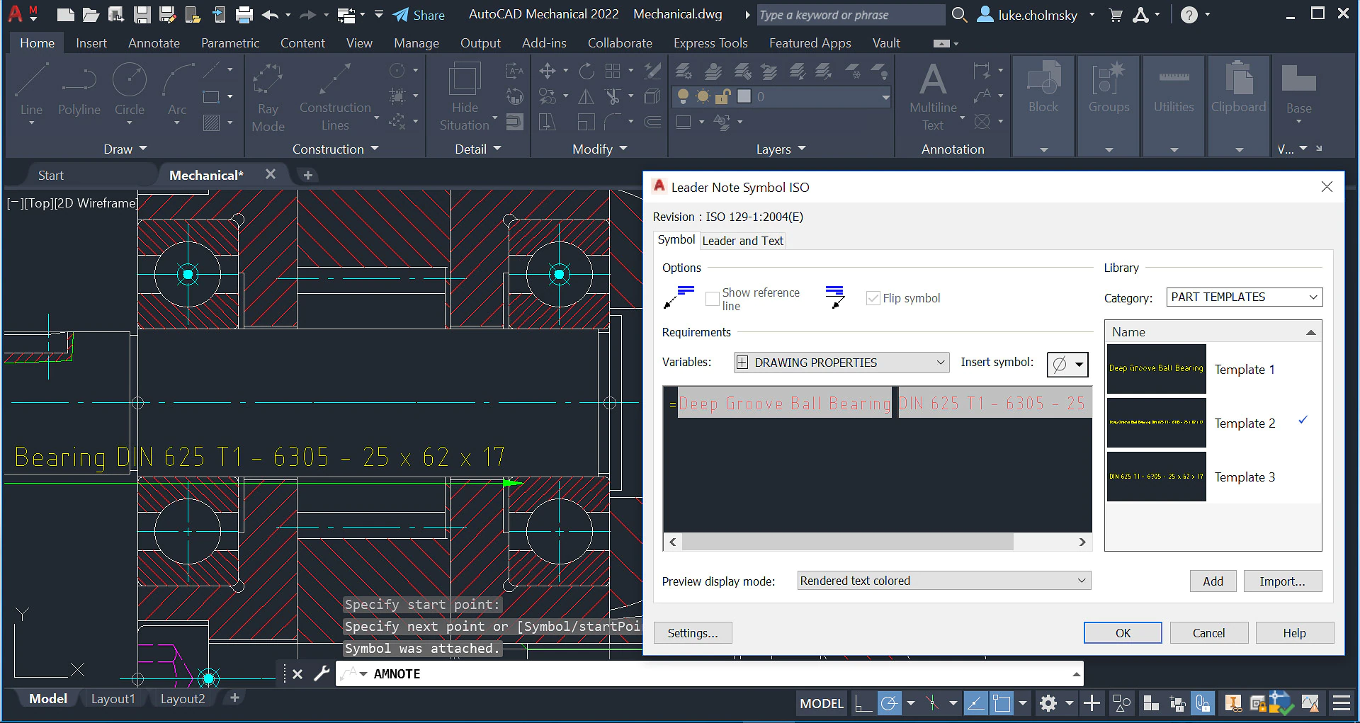
Create a leader note and, attach it to an object in the drawing area.
Summary
Notes can contain plain text or formulas. A predefined set of templates containing formulas are available in the symbol library. An appropriate template is automatically applied when you attach a note to an object. Hence, notes automatically display meaningful context-sensitive information immediately upon creation.

Use the AMNOTETAB system variable to turn the Note contextual tab on or off. It opens the Note dialog only if the system variable is set to 0.
List of Prompts
-
Reorganize
- Aligns two or more leaders to one another.
- Select note – Specifies the leader note symbols to align. Press ENTER when you are done.
- Horizontal – Aligns the symbols horizontally. Click in the drawing area to place the symbols.
- Vertical – Aligns the symbols vertically. Click in the drawing area to place the symbols.
-
Library
- Specifies that the symbol text is obtained from a template in the symbol library.
-
- Category – Specifies the name of the category of the template you want to apply.
- ? – Lists the names of the items you can select.
- Symbol name – Specifies the name of the template you want to apply.
-
Start point
- Specifies the position of the leader arrow. If you attach the symbol to an arc, circle, ellipse, or spline, AutoCAD Mechanical toolset automatically determines the start point and does not display this prompt.
-
Next point
- Specifies the location of the next vertex of the leader.
-
Note:
- If you attach the symbol to an arc, circle, ellipse, or spline AutoCAD Mechanical toolset forces the leader to be perpendicular to the attached object. To override this restriction, press the Toggle Symbol Leader Orthogonal Mode key (SHIFT + F, by default) as you move the cursor.
- If you attach the symbol to a line, AutoCAD Mechanical toolset does not enforce this restriction. To make the leader segment perpendicular to the attached line, move the cursor so that the leader is approximately perpendicular, and track along the alignment path that is displayed.
-
Symbol
- Places the symbol at the most recently clicked location.
Drawing border and title blocks
Customize drawing borders and title blocks to work with your system. Each of these items exists as separate .dwg files, which you can copy and modify to optimize your configuration.
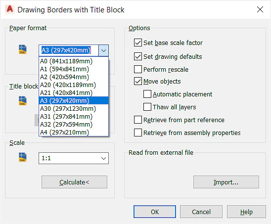
Drawing borders are shipped as *.dwg files that contain specific formatting objects, which are required by the AMTITLE command.
AutoCAD Mechanical toolset ships with several drawing border dwg files for each supported drafting standard and paper size. For example, the drawing border for A4, landscape for the JIS standard is jis_a4l.dwg. You can copy these files, customize them and configure your system to use the customized drawing borders.

Item Description
1) Inner frame, typically drawn on layer 0
2) Outer frame, typically drawn on layer AM_BOR
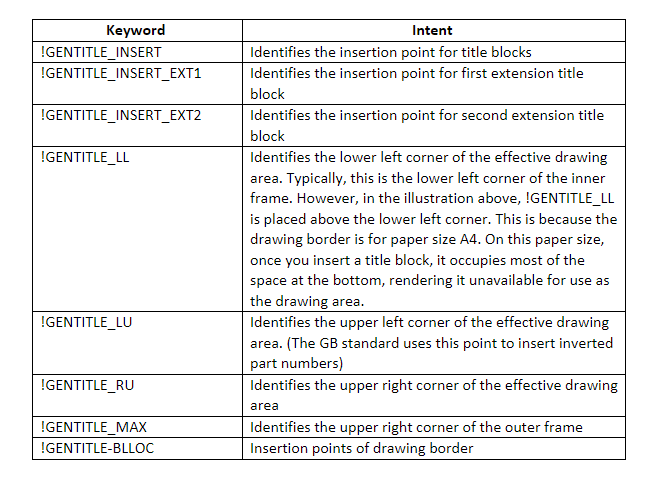
3)TEXT object containing a keyword, which identifies a key position.
The insertion point of the text objects identifies key positions. The AMTITLE command uses these points to implement various options. For example, it uses the insertion point of the text !GENTITLE_INSERT as the insertion point of the title block. The keywords and the options that are available vary from drafting standard to drafting standard.
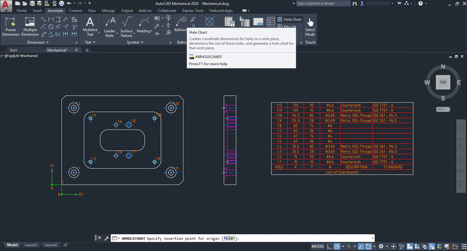
Drawing detailing
Use intelligent drafting tools made specifically for mechanical design. Boost drawing productivity and efficiency with reusable detailing tools such as Centerline, AMSHIDE, Hole Charts, and Scale Area for Viewports.
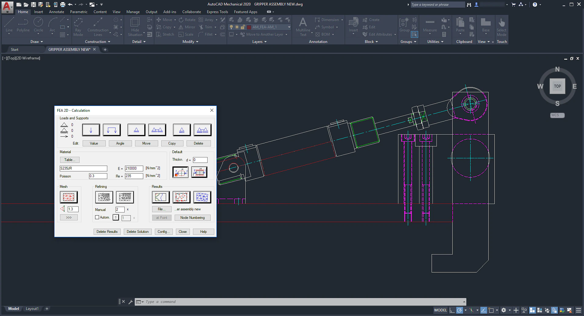
2D calculations
Combine automatic part creation with drawing automation to get the best value. Efficiently analyze designs and perform 2D calculations such as FEA, Shaft Calc, and Moment of Inertia.
Autodesk combined seven industry-specialized toolsets into one version of AutoCAD, and one of those is the Electrical toolset. You can read more about this change here.
Need to find out which AutoCAD is right for you?
INDUSTRIES: MEP Engineering