


Exploring AutoCAD Layers
By Microsol Resources, Graitec Group | CAD
Layers are the basic method of organizing the position of objects in 2D and 3D graphics. Many architects implement AutoCAD layers to control the layer properties of their drawings on a page.
These layer properties include line weight, line type, color, and description. They are generally used to determine the appearance of objects on layers in AutoCAD.
Different forms of layers have their unique names. Interestingly, you may choose to group them alphabetically or numerically, depending on the requirements of your project.
In this article, we will discuss the definition, properties, creation, and management techniques of layers in AutoCAD.
What Are Layers in AutoCAD?
In AutoCAD software, layers are drawing planes that help you to easily control the properties and visibilities of objects. Examples of these objects include:
- Lines
- Images
- Blocks
- Tables
- Spreadsheets
You can use layers to manage or control the visibility of objects by activating the on/off command.
Similarly, you can also control the visibility of objects by using the freeze/thaw command.
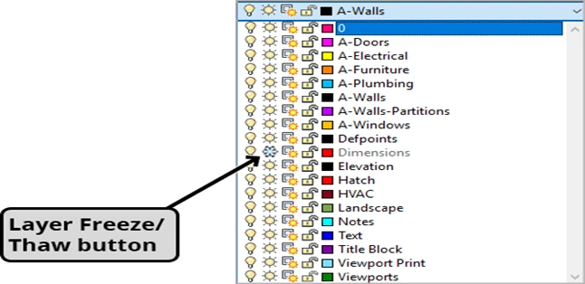
The only difference between the freeze and turn off command is that the freeze unloads the layer from its memory. The table below contains other possible basic layer commands in AutoCAD plot settings.
| Basic Layer Commands | Function |
| Lock & unlock layers | It protects the file drainage and prevents accidental changes
|
| Make current layer | It activates an existing layer to record the latest update in AutoCAD geometry
|
| Match layer | It matches an object with the plot style created in AutoCAD
|
| Change to current layer | It undoes the last changes in the layer settings by changing the layers list from layer 1 to layer 0 (i.e the current layer)
|
| Copy object layer | It copies all the selected lines into a new layer button created in the layer properties manager
|
| Layer walk | It displays objects on selected layers by showing all the hatches, lines, and blocks
|
Keep in mind that one drawing can have many layers, depending on the dimension, style, and complexity of the drawing. You can use each layer to draw a specific object type. For example, you can complete the drafting process by using:
- Wall layer to draw walls
- Door layer to draw doors
- Window layer to draw windows
- Column layer to draw columns.
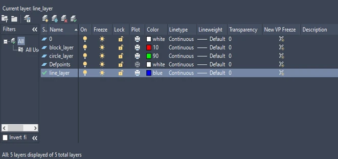
Layer Properties
Layer Properties are responsible for controlling the visibility of different objects within a drawing. Here is a list of the main layer properties in AutoCAD:
- Name
- Color
- Linetype
- Lineweight
- Transparency
Each layer in AutoCAD has a specific name that makes it unique in the layer tab. For example, in the diagram below, the default layer is called ‘reference’, while the current layer is called ‘walls’.
These names make it quick and easy for architects and engineers to find a certain layer by using the layer properties button.
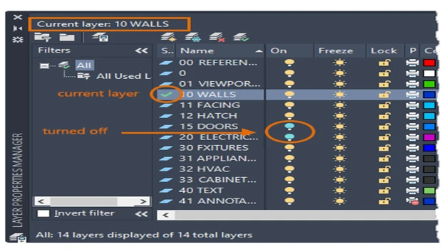
To assist in visual distinction, all layers are created with different colors in the layer manager palette. For example in the above diagram, the reference layer is assigned a red color, while the current layer is given a blue color.
Layer color can also be useful for visual interpretation. This may look surprising, but in places like California, Texas, New York, Florida, and Illinois, people recognize blue color as an essential part of plumbing.
Therefore, AEC professionals use it as the appropriate color for plumbing fixtures, such as water pipes, sinks, and drainage pipes. Another important layer property is the linetype, which basically refers to the style of lines or geometry of the layer.
Some common examples of linetype include solid lines, dotted lines, and dashed lines. They play a crucial role in layer management and object selection, ensuring precise representation of graphics.
Furthermore, each line on a layer has a thickness that ranges from 0.10-1.50 mm, depending on the line weight of the specific layer. This means that the lines can only be plotted with a minimum thickness of 0.1 mm and a maximum thickness of 1.5 mm.
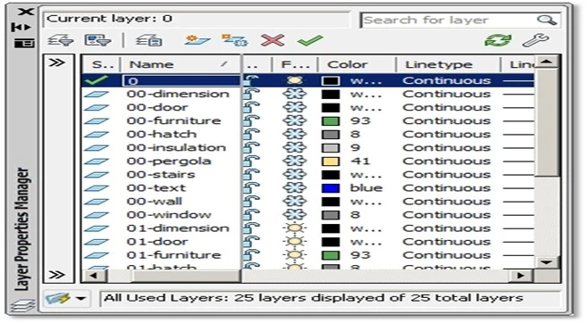
Creating & Managing Layers
You can create and manage layers in the layer manager palette. To carry out this process, you need to first open the home tab layer panel > Click on the layer properties button and select layer properties manager. Now, activate the layer manager by using “LA” as a shortcut.
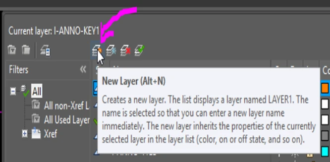
In the layer manager, you can create new layers with the shortcut key, Alt + N. By default, the new layer will be named Layer 1. However, you can rename the layer with a name that best fits your project.
The next step is to select a suitable color, linetype, and lineweight for the new layers. To do this, simply navigate your system cursor to the column containing color, then select a unique color for each layer.
Now, move the cursor to the next two columns containing linetype and lineweight, then select the appropriate parameters that fit the rows in each column.
To effectively manage the newly created layers, you can use the basic layer commands, which we earlier discussed in the previous section of this article.
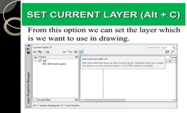
In addition, It is important to take note that the shortcut key to delete a layer is AIt + D, and the shortcut key to set a layer as the current layer is Alt + C. Therefore, the shortcut to most layers is simply Alt + the first letter of the layer’s name.
Advanced Layer Techniques
Elements are separated into different layers through the help of the advanced layer techniques in AutoCAD. These techniques include:
- Layer states: The primary role of the layer state is to assist you in managing many layer configurations at the same time. For example, when drawing a large building plan, layer states help you to easily hide the door layer while working on the wall layer.
- Layer filters: To improve the visibility of relevant layers in AutoCAD, try using layer filters to first filter the layer properties before using the freeze/thaw command.
- Layer transparency: This allows the lines and columns on a top layer to appear white or transparent, making the layer beneath more visible in 2D drawings.
INDUSTRIES: Architecture, Buildings, MEP Engineering