Understanding Dimension Lines in Engineering and Design
By Microsol Resources, Graitec Group | CAD
In engineering drawings, dimension lines are lines that indicate the many measurable features in your drawings. They define the size, shape, and placement of items in the drawing and are necessary for accurately communicating design specifications.
Dimension lines are a key part of how the drawing will be read and understood by your reader, ensuring all important details cannot be misinterpreted. Without dimension lines, a finished drawing is simply a print-out of random lines and shapes!
Essential Components of Dimension Lines
Dimension lines should not be confused with other visible lines in your drawing. Dimension lines contain specific features to differentiate themselves. Below you will find a list of features that will allow you and the reader to distinguish dimension lines from other items in the drawing.
Numerals
Dimension lines show numerical annotations that specify the exact measurement of a feature, such as length, width, height, angle, etc. This value is typically found at the midpoint of the line, formatted according to the drawing’s unit system (mm inches, degrees, etc.). Tolerances (±0.2mm) may be added to indicate acceptable variation in the finished part. Sometimes, symbols like Ø for diameter or R for radius can be used. Dual dimensions (2.54 cm [1 in]) show both metric and imperial units for multipurpose uses.
Extension Lines
Extension lines are thin lines that extend from the object you wish to measure to the dimension line, showing exactly what points are being measured. They begin just outside the object’s edge, with a small gap, and don’t touch the measured object directly to avoid clutter. Extension lines improve clarity by linking dimensions to specific features. Note that it’s important to avoid intersecting extension lines with other features in the drawing to avoid confusion.
Arrowheads
Arrowheads on dimension lines mark the endpoints of a measured distance or angular dimension. They are usually small, filled triangles but can vary in style depending on your drawing specifications. Arrowheads allow for precise measurement boundaries and are typically sized proportionately to the line to prevent crowding the drawing.
Types of Dimension Lines in Engineering
In engineering drawings, there are multiple different dimension lines that all serve a different purpose. You will likely use most, if not all, of these different types once familiarized. You will find a description of several of these linetypes below. The visual snippets in the table are taken from the AutoCAD dimension drop down.
| Measurement | Description | Visual |
| Linear |
|
|
| Aligned |
|
 |
| Angular |
|
 |
| Arc Length |
|
 |
| Radius |
|
 |
| Diameter |
|
 |
| Jogged |
|
 |
| Ordinate |
|
 |
Practical Applications of Dimension Lines in Engineering Design
Now that you have become familiar with the different dimension linetypes and how they differ from other items found in your drawing, I’d like to take you through some examples of where you might use them. Understanding where and when to use these different dimension lines will be pivotal in your design journey.
Linear Dimension Lines
Linear dimension lines are generally the most common in engineering drawings, applied wherever straight (horizontal or vertical) distances need to be measured. One example would be if you are defining the basic dimensions of a rectangular part, like a window. Each side of the window will have a linear dimension, specifying exact dimensions for manufacturing. This ensures that parts will fit properly, and installation issues can be avoided.
Aligned Dimension Lines
Aligned dimension lines are ideal for measuring diagonal or sloped elements, providing true-length measurements along the feature. For example, the length of a chamfer on a steel rod would be measured with an aligned dimension. This type of dimension is also helpful in architectural drawings, where a sloped staircase would need to be measured.
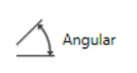
Angular Dimension Lines
For angular dimension lines, let’s use the example of a gear teeth or a spline shaft used in industrial equipment. The angular measurements of the gear teeth and shaft are critical dimensions. Smooth operation of the assembly will rely heavily on proper dimensioning in the drawing. Proper tolerancing of these dimensions will also directly impact part performance.
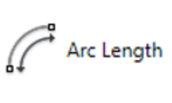
Arc Length Dimension Lines
A practical use-case for measuring an arc-length could be custom ductwork in an architectural floor plan. Ensuring accurate dimensioning of the curved metal piping will be crucial during installation. Another example could be measuring the curved elements of metal conduit in an industrial floor plan.
Radius Dimension Lines
Radii in engineering drawings are incredibly important. Take for instance designing metal casting molds for vehicle engine parts. Sharp corners that would be produced without proper radial dimensioning act as stress concentrators once in service. Stress concentrations in critical components can lead to catastrophic failure of high-value components in an assembly.
Diameter Dimension Lines
Diameter dimensions become more important when dealing with cylindrical features such as pipes or holes in a drawing. To be more specific, the diameter of a hole to be drilled for a fastener needs to be properly defined to ensure precise fit during assembly. The tolerances on diameter dimensions will also be a specifically important annotation to keep in mind.
Jogged Dimension Lines
As previously mentioned, jogged dimensions are exclusive to features with a large radius. For example, the large arcs that would need to be defined on an arch bridge. The jogged dimension will provide the radius measurement but with a shorter, zig-zag dimension line to avoid clutter in the drawing. Civil engineers commonly use jogged dimension for their large-scale features.
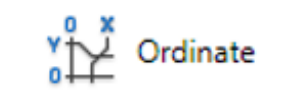
Ordinate Dimension Lines
After specifying an origin, ordinate dimensions allow for exact placement along the X and Y coordinate system. Commonly seen in critical dimension applications such as circuit boards for electronics, ordinate dimension lines provide accurate placement of all features. This dimensioning style prevents cumulative errors and makes it easy to work with complex drawings that rely on perfect placement.
INDUSTRIES: Civil Engineering, MEP Engineering, Structural Engineering


