Revit+Showcase = Classy Design Presentations with Minimal Effort
By Microsol Resources, Graitec Group | BIM
One of the neat things about using Revit is the fact that most Building components that come with the software or provided by manufacturers have Parametric Material information; In this context ‘parametric’ simply means that one is able to change how a particular component is displayed in terms of its color/texture/transparency and the like without performing complex gymnastics. What this means to designers is that they can now create multiple options and configurations by simply moving geometry around and flipping a few menu options. This post assumes that you already know how to do this in Revit and will focus on what happens next. This workflow using AutoDesk Showcase with Revit is immensely useful for all designers especially the ones dealing with planning and consensus building as is usually the case with Health-care and Pharmaceutical projects. Quick turnaround times coupled with convincing renderings make this workflow the nifty ninja among stodgy medieval knights using AutoCAD/Sketch-up/3DMax/freehand workflows.
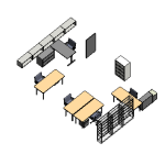
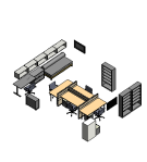
I used the excuse of making furniture options for our Tech Room as the pilot project to test these tools when they were first released. Below are four furniture configurations set up using ‘Design Options’ in Revit 2013.
These views were created using Section Boxes and the ‘Realistic’ visual Style in Revit. The next step was to multiple views for the purpose of Exporting to Showcase either directly using the Building Design Suite Workflow option or via the FBX file format. Creating multiple views is a good idea is it lets us go through multiple iterations of the design without having to configure view visibility every time. The premise is to create multiple components out of the Revit file and then control the visibility of each component independently within Showcase.
For this project, I broke out the file into the overall building, the sectional building and the four furniture options. In addition to this, I am going to use the Material Line-up feature within Showcase to display multiple material options within the same geometry configuration.
Getting from Revit to Showcase is a fairly straightforward exercise. Below is an example of the first exported part-model.
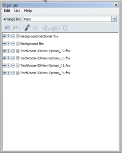
 Like I mentioned earlier, all the material properties that are native to the geometry in Revit will port into Showcase. There is absolutely no additional work required. Once the various models (part-models) are brought into Showcase, you can control the visibility of the various parts using the ‘Organizer’ to turn on or off parts in way very similar to Auto-CAD or Photoshop ‘Layers’.
 The next step is to create ‘Alternative Lineups’ by capturing snapshots of Visibility, Materials and Positional Configuration. Using the Visibility Line-up, I can capture the various options within the model.

Creating Line-ups are as simple as selecting the Type of Line-up you want from the Drop-down menu.
One can then select all the parts that should be part of an Alternative and assign it to the Alternate by selecting ‘Add to Selection’. Do take a note of the other options that are available in this menu such as the option to set a Thumb-nail Image and so on. The idea is that these Thumbnails will serve as Buttons that show a particular Visibility Line-up whenever they are selected – either during the course creating a presentation or during the actual presentation or, when exported as a webpage for the viewer to get access to.

Material Line-ups can just as easily be created using the Autodesk or Showcase Materials Library. New Materials can be easily created using the Procedural process that was first begun in 3DStudio Max workflows. Below is a screen shot of the Floor Material Alternative Line-ups.

Positional Line-up works in a way similar to the earlier Line-ups. This time however, you can use the Gizmos that appear when an object is selected to (re)position the object and capture its new position. Selecting the Base Plate of the Gizmo causes the numerical transform controls to appear and this can be used to accurately position objects within the project.

The complete project will display objects based on the configuration of Line-ups.

The next step is to create Storyboard slides that can be activated using the Thumbnails. This can be easily accomplished through the right-click menu on the Alternative Line-up and then using the Properties Dialog on the Slide to adjust the timing and Alternative configurations.
Finally the Shots can be organized into a Storyboard complete with time-specifications. This Storyboard can be published into multiple formats including online Flash presentation modes.
Click on the Image below to view the flash presentation. Make sure you have a high-speed connection…
INDUSTRIES:


