


Revit Adaptive Components: Practical Archetypes: The Vaulted Ceiling – Part One
By Microsol Resources, Graitec Group | BIM
If you had anything to do with buildings in New York, chances are that you may have encountered elaborate, arched or vaulted ceilings. Even if you weren’t designing the space ‘in-the-manner-of’ the gilded age, more often than not, you would have documented what exists and surgically excised or implanted your work into the existing fabric. This is when you realize that these marvels of geometric complexity aren’t that perfect. A fairly accurate survey of all the crowns and spring-points of the arches will tell you that all of them are off by a few inches from the ideal geometrical vision of Architecture. Unfortunately, it is a few inches that usually stands in the way of possible and impossible within which most designers have to work with. So, the challenge here is: how do you build a ceiling using Revit that sufficiently accurately mimics the geometrical anomalies of the real world? The answer surprisingly is not that simple…
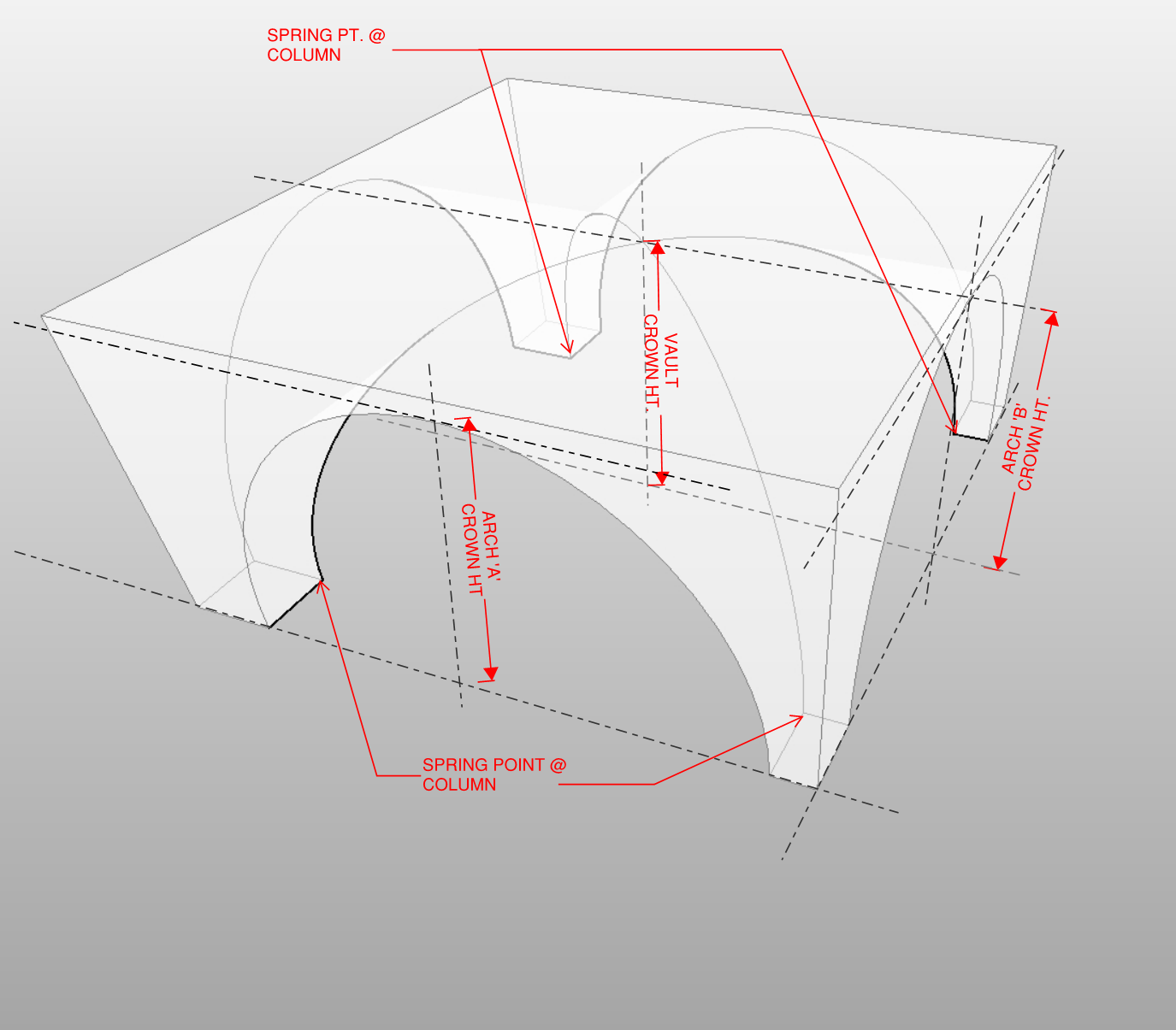
Before we go ahead, lets take a look at the kind of survey points one can expect to receive for EVERY bay in the vault. On the left is a diagram with all the points one can expect to get from the surveyor or at least for each bay. Sometimes, a single vertical section through each of the orthogonal axes of the space is enough to extrapolate the information needed. The idea is that one can then translate these points to linear dimensional parameters within a family to drive the geometry.

In the test project, I’ve set up a simple spreadsheet that captures the data in a pseudo-graphical manner. (Note that things can get random pretty quickly if you don’t keep all the pertinent information organized for your long-term memory).

Now is when the fun begins! We know where the columns are (at the intersections of the grid-lines), so the component that we build will be placed by picking the grid-line intersections (or, automatically by X-Y coordinates) and then we could go in and change the height parameters to ensure that the geometry conforms to the real-world heights at the crown and spring point. It is often an exercise in futility to attempt to connect the real world points with an ideal curve. This being the case, one has to build a geometry that coincides with critical real-world points such as the lowest (spring points) and the highest (crown points) at each bay, and has a curvature that only approximates the real world.
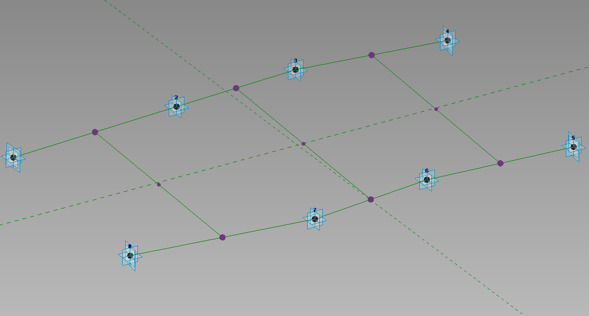
First off, I’m going to build an armature; a Rig that corresponds to the eight Column Points for each bay. This can be done by laying out a base bed consisting of eight Adaptive points with interconnected Reference Lines wherever Midpoints are needed (for the mid-point of the arch in plan).
Next, one has to elevate four points for every Adaptive Point. These four points will serve as Spring Points for the Vaults as supplied by the Surveyor. Raising four points and controlling their height is not only tedious, but they can clutter up the screen. A more elegant solution can be achieved by nesting another Adaptive component containing four corners and a Height parameter as shown in the image below:

The Column Capital Adaptive Component is then placed at each of the eight Adaptive Points within the Rig family and then connect the nested height and width parameters to the corresponding parameters within the Rig family.

Now that Spring Points are defined, the next logical step would be to devise a way to parametric control the height of the Arch/Vault crowns. This can be quite easily accomplished by using the mid points of the Reference Lines (hosting the reference point on the reference line and setting the ‘Normalized Curve Parameter’ to 0.500000).

As usual, connect the parameters to the Crown Height Parameters right-away. Waiting to connect parameters until after all the geometry is in place is risky for two reasons – one is that you cannot flex to make sure it works and two: if something does go wrong, it is hard to find the source of the error across many layers of work. The next step is to create a wireframe outline of all the separate surfaces/solids that make up the vault bay. This is done by create a ‘spline-by-points‘ using the existing Reference Points.

The bones of the Rig is now complete. We will now create Adaptive components that can be nested within the Rig and capable of flexing with the Rig. These are the components that will be visible in the project environment.

Notice that you need about three adaptive points if you want a spline that incorporates a curve and only two if you need a straight line. The component on the left (above) has two straight-line segments and two curved segments defining a solid with a parametric thickness. The component on the right (above) has two curved segments and one straight-line segment. Another parameter that might be worth considering for these components would be the material definition. Once the two adaptive components are tested and ready to go, they can be placed in the Rig. There is one more step that needs to be completed before the components can be placed. Notice that the components have two extra Adaptive Components than what is provided for in the Rig. To accommodate the extra points, we can add those points either as mid points or ‘Third-points’ (Normalized Curve Parameter of 0.33 or 0.66 ). The idea is that the three-point spline defining the side of the solid will approximate within a fraction of an inch the real-world curvature of the vault.


Once completed, the Rig is now ready for placement in a Conceptual Mass environment.
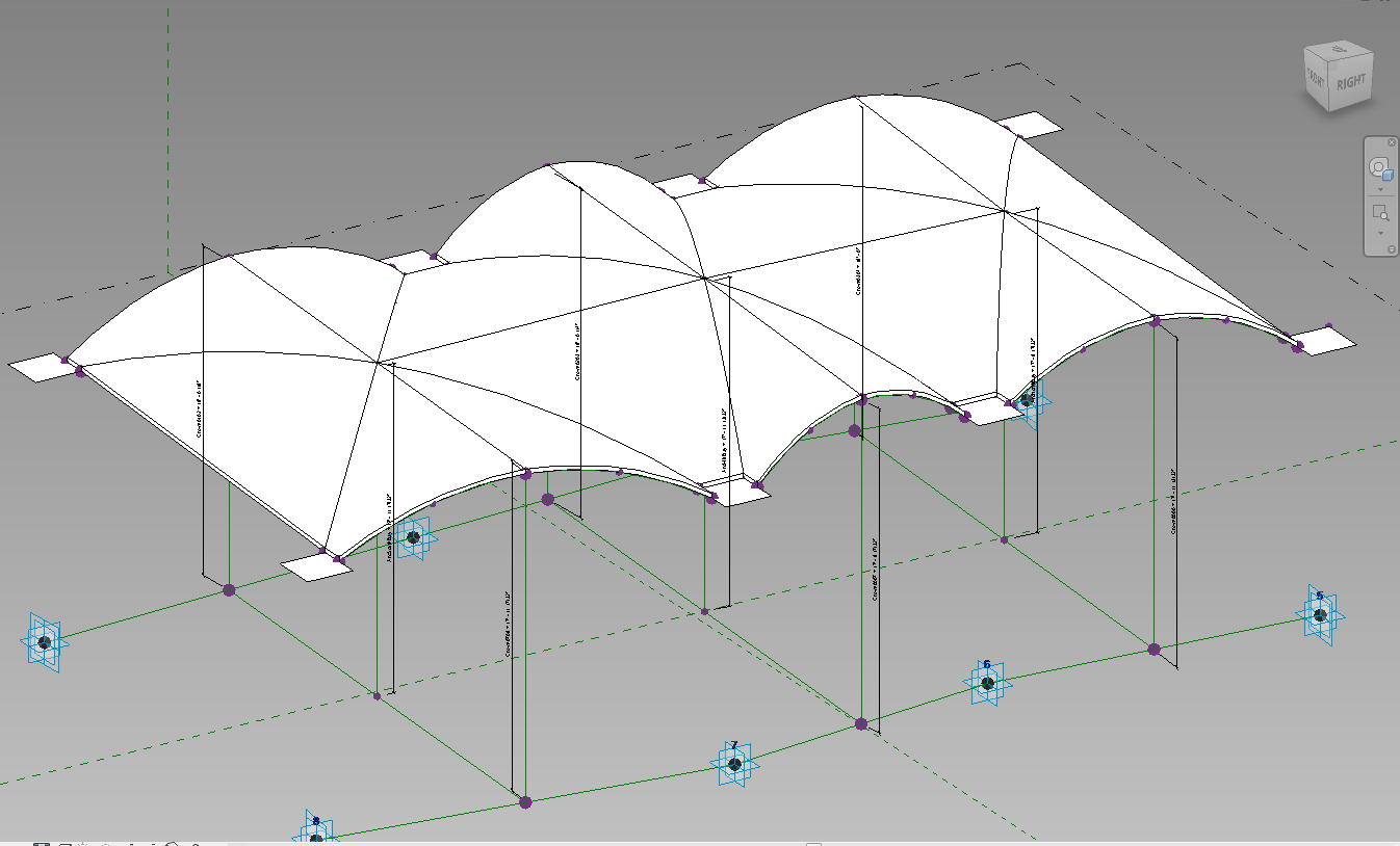
In part two, we’ll look at placing the Rig shown above in a Conceptual Mass environment and easily creating types for controlling the height parameters. Additionally, we’ll look at automating the placement of the Rig using some modified sample code from Nathan Miller.
INDUSTRIES: