


Revit Adaptive Component: Practical Archetypes – Curved Glass Curtain Walls
By Microsol Resources, Graitec Group | BIM

Curved panels are particularly gnarly! Curved and Non-rectilinear are more so. This is one of those situations where you don’t have a choice but to use Adaptive Components.
In this post, I’m going to attempt to show how simple the building of a curved and trapezoidal panel can be. So, bring out the rusty trigonometry toolbox (or googling skills) and let’s get started!
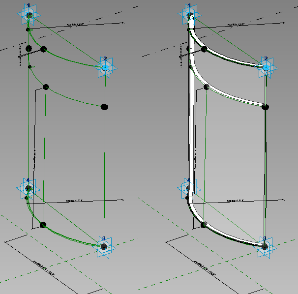
The first step is to get adaptive points on a plane. I chose the vertical Front/Back Plane. The beauty of Adaptive Components is that they need not be built exactly the way they are going to be placed on a surface. So a fair approximation of the final form will suffice. The important thing to note is the ‘Orientation’ parameter. This should be set to ‘Orthogonal to Family’ for the purposes of this exercise. The Autodesk Revit Wikihelp has more information on this setting in case you are curious.
The next step is to host arcs on the reference plane created by the reference line connecting the top two and bottom two adaptive placement points. The key to keeping the arc attached to the adaptive points is to parametrize the radius to an instance parameter.
Getting the horizontal mullions to follow the arc is then accomplished using the profile and sweep method, and I will not go into the details of how to do this (see any basic Mass or Adaptive Component video to get the idea). Please watch the video at the end for the entire sequence of operations (in case this blog is too cryptic). The next task is to create the vertical mullions. The challenge here is to ensure that the vertical mullions rotate in sync with the ends of the arcs at the top and bottom. We’ll need to dust off our high-school trigonometry textbooks for this endeavor. Creating the mullion geometry is pretty straightforward – have to profiles and create a blended extrusion between the two; rotating the millions is a bit more complicated. The key is to host the two mullion-profiles (one on either end of the mullion) on reference points that are in turn hosted on the reference line connecting the top and bottom adaptive points.
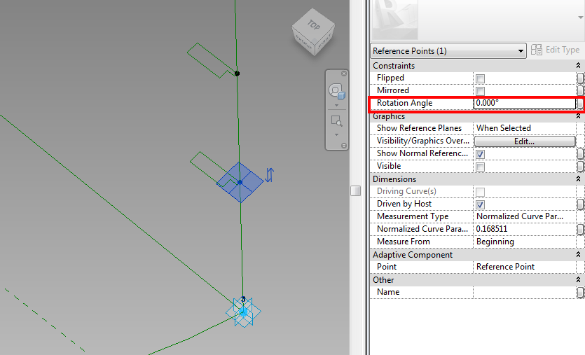
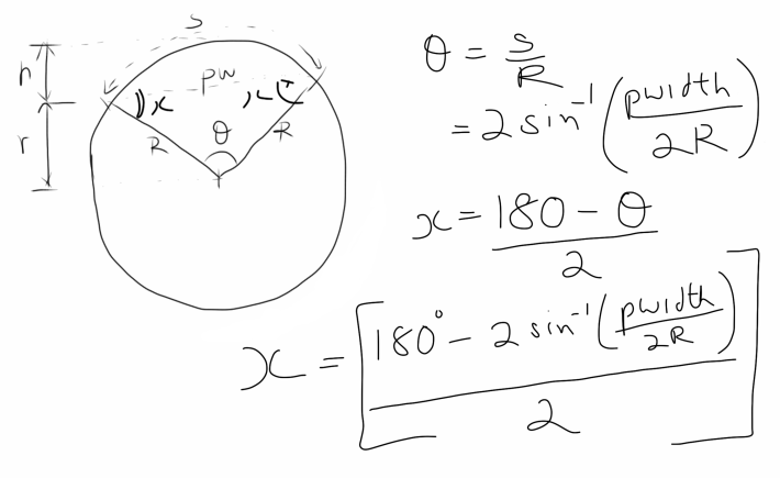
The rotation angle parameter can be derived as a function of the radius of the arc and the width of the panel. If we were to abstract away the panel as a segment of a circle, the arc length is the product of the Radius and the internal angle described by the arc at the center of the circle (denoted by ‘θ’ in this case – and, to be fair, the Greeks did discover this long, long ago!). Once θ is determined, we can be used the property of isosceles triangles (the angles between the equal sides and the base are equivalent), along with the property of 3-sided polygons (sum of the internal angles will equal 180 degrees) to determine the rotation angles of the vertical mullions.
The width of the panel can be obtained by setting up a reporting parameter for the bottom two adaptive placement points. From here on it is just a matter of setting up a negative version of the same parameter to enable rotation of opposite mullions. For the sake of brevity, I have set up the parameters for the top and bottom-of-glass parameters to coincide with the top and bottom positions of the vertical mullions.

What’s left is the fleshing-out of the rig. The key at this point is to ensure that the Rig is flexed at every step to ensure that all components work as expected.
Curved Panel Adaptive Component from Francis on Vimeo.
CAVEAT EMPTOR: Adaptive components are particularly finicky when it comes to placement. Once the entire panel is done, it is often a good idea to flex the panel to extreme dimensions to get all or some of the annoying ‘inaccuracy’ errors out of the way. It appears as though that once these errors are encountered in the family editor environment, the families would not have a problem in the Mass environment. However, if this flexing is encountered directly in the mass environment (and one assumes that the component develops an inaccuracy error internally), then the component will insist on deleting itself. In the case of this particular family, it is less painful to specify the family types with the corresponding radii within the Family editor rather than loading into a mass family and then specifying types there. It is also a good idea to approximate the width and height of the parameter within the family editor to the final width and height.
On some surfaces, the Adaptive Component may simply refuse to stick. If these panels are in the middle of the grid, I’ve had a lot of success in placing the adaptive points in the anti-clockwise direction and then ‘Flipping’ the component using the ‘Flip’ Instance Parameter to reverse the component. In some cases, this may not work at all and I have found that these are often in components that border another surface and probably caused by conflicting normals on the edge nodes. In these instances, the only option is to recreate the host node-grid or attempt to embed the component within a Curtain Wall-Pattern family.
It’s unfortunate that Autodesk would not release any formal documentation on this toolset except for a few videos by third parties as of today. Some of the more outlandish experiences include the functionality of the tools changing over the course of the work session. For example, at a recent demo, when model lines were used to generate a form, the model lines were converted into reference lines after the form was created (with Rob Narracci as my witness). So, it is a good idea to restart the computer and perform a ‘walkabout’ every so often rather than trying to figure out if its you or the computer that’s loony (I’m afraid I can’t blame this behavior on memory leaks as a result of shoddy coding as that would be libelous).
Okay, there is a bit of fudging when it comes to the trapezoidal panels – the top mullion cannot exactly be an arc – it has to be a conic section. I’m sure there is a way to get the top mullion to describe the conic section if you throw enough time at it.
INDUSTRIES: