


3D Printing a Civil 3D Surface
By Microsol Resources, Graitec Group | 3D Printing
There’s an old saying that I’m sure you’ve heard that goes “you won’t know until you try”. While it’s one of those phrases that’s been around long before computers were in every office, it remains modern enough to be very relevant to working with software. I found myself thinking about this phrase when a client asked if they could have a Civil 3D surface printed on our 3D Printer, a 3D Systems CJP Project 660Pro.
It may sound obvious, but the only prerequisite for printing anything in 3D is that the object has a width, depth, and height. A Civil 3D surface object, while made up of X, Y, and Z points, is only a two-dimensional object since it has no thickness. The first hurdle would then be to add some “thickness” or height to that surface to make it printable.
If you are a Civil 3D user you may think, “well that’s easy, just use the Extract Solids from Surface”. And while that is exactly what crossed my mind when I started thinking about how to print a Civil 3D surface, it turns out that the Extract Solids from Surface does not work for very complex geometries. This command is great for extracting out solids from corridors and smaller surfaces, but it couldn’t generate a solid for a heavily graded 70-acre subdivision with 100’ of elevation difference between its low and high points.
As I didn’t have rights to use the surface described above when writing this blog, I am instead using another surface to illustrate the steps. For all intents and purposes, these steps will work for any surface.
Exporting Civil 3D Data for 3ds Max
Met with failure, I turned to 3ds Max, the most powerful geometry editing software in the AEC Collection. I had many options to choose from when importing the Civil 3D surface into 3ds Max, but I narrowed it down to two options.
The first option would use Civil View to exchange Civil 3D object data with 3ds Max using a VSP3D file. The second option is to export a LANDXML file from Civil 3D and then import that file into 3ds Max.
I ended up choosing the latter option since it automatically generated polygons in the various HIDE boundaries found on the Civil 3D surface I was using. While I lost a marginal amount of fidelity from the original surface, using LANDXML created a gapless surface which we preferred for the 3D Print.
Exporting a LANDXML file from Civil 3D is as easy as right-clicking the surface in the Prospector and selecting Export LandXML… Importing the LANDXML file into 3ds Max is equally simple; click on the File menu, choose Import and select the LANDXML file. You should uncheck Smooth Surface in the Object Creation Options to preserve the Civil 3D surface geometry.
Creating a watertight model
Unlike the Extract Solids from Surface command in Civil 3D, I simply had to create a watertight poly surface or mesh in 3ds Max. A watertight model is defined as an object that doesn’t have any naked edges. McNeel’s website makes a great analogy when defining a watertight object; “another way to understand a solid is to see it as a balloon. If there is even a pin prick size hole, it will deflate. Thus it is not air/watertight, not volumetric. A solid is a volume. A solid is its outer surfaces, once they are completely joined”
The LANDXML import provides me with a editable mesh in 3ds Max. To manipulate the geometries in the mesh to create the watertight solid I previously mentioned, follow these steps:
- Select the Editable Mesh and choose the Element sub-object levels in the modifier stack
- Click on any part of the surface and you will see the entire mesh highlight
- In the Edit Geometry rollout enter in an Extrude value; I will use 500’
- Switch the to the Edge sub-object level and press the Select Open Edges button in the Edit Geometry rollout
- With the open edges selected, toggle the Top view and select View Align from the Edit Geometry rollout. This will flatten the edges to the same Z value
- Choose the Face sub-object level and drawing a Crossing Selection through the recently extruded faces
- Select the Detach button from the Edit Geometry rollout to create new object from those faces
- De-select the original mesh and select the detached mesh
- Right-click and choose Convert To: Convert to Editable Poly from the Transform Quad
- Select the Editable Poly object, activate its Border sub-object level, and select the open border
- From the Graphite Modeling Tools, select Cap Poly from the Geometry (All) Panel in the Modeling ribbon
- Activate its Polygon sub-object level and select the bottom polygon cap
- Press the W key to activate the Move gizmo and raise the Polygon along the Z axis to the desired height
- Deselect all sub-object levels, select the Editable Poly
- Right-click and choose Convert To: Convert to Editable Mesh from the Transform Quad
- De-select the detached mesh and select the original mesh
- Select Attach from the Edit Geometry rollout
- Choose the detached mesh to join it to the original mesh creating a watertight mesh
Despite the extensive list of steps, the process is straightforward if you are familiar with 3ds Max. The video below illustrates all these steps to make it easier to follow along.
Create a file for 3D Printing
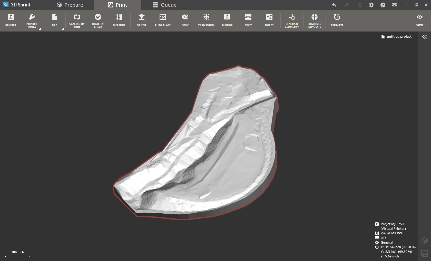
Once the geometry has been edited to be watertight, export the geometry to an STL (STereoLithography) file. In order to send our 3D print jobs, we use an application called 3D Sprint. 3D Sprint can import the STL, check for any geometry errors, and scale the model so it can be printed. The screenshot below shows the 3ds Max geometry ready to be printed.
INDUSTRIES: